2-20
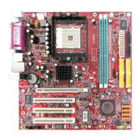
MS-7145 M-ATX Mainboard
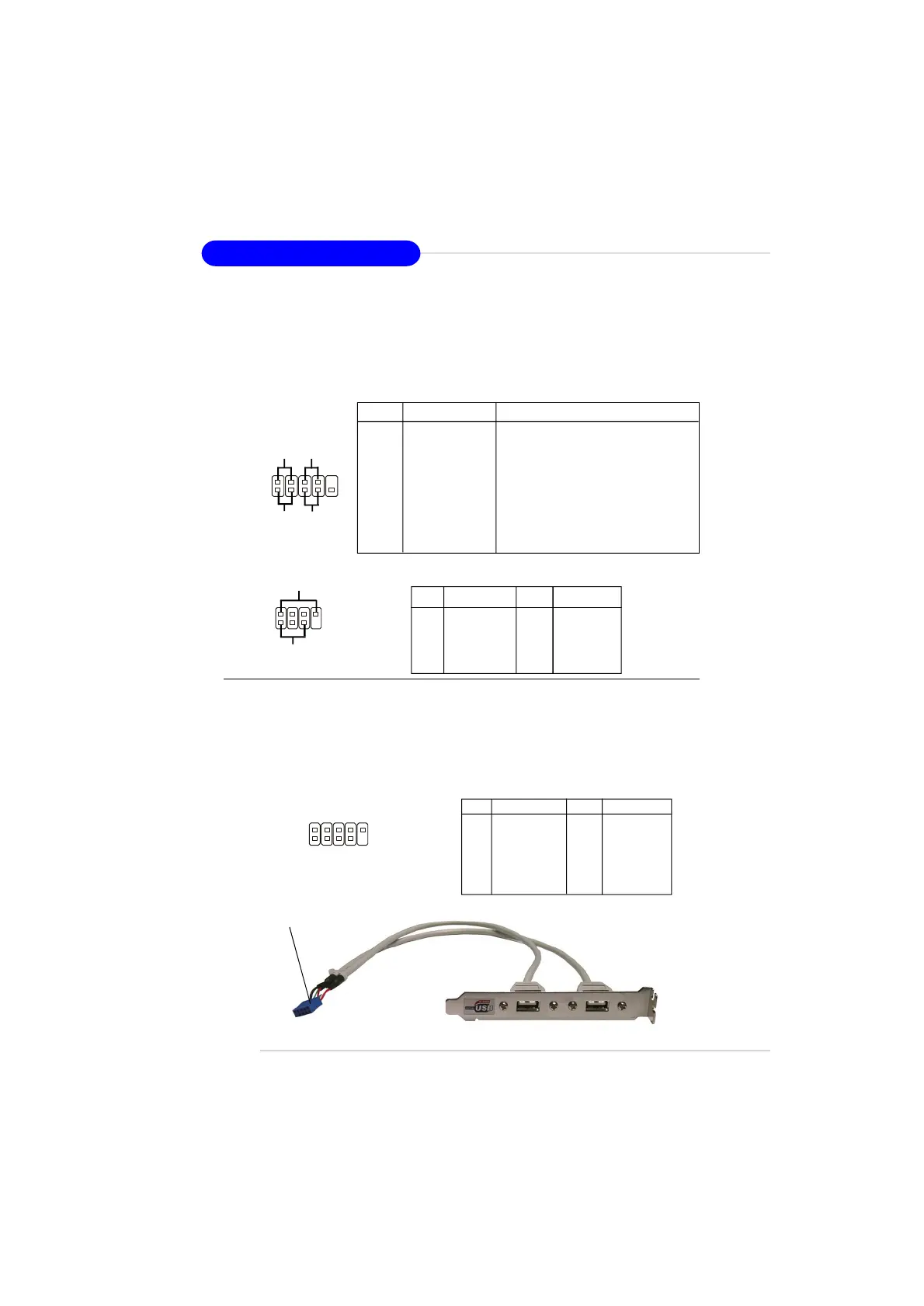
Front USB Connectors: JUSB1 / JUSB2
The mainboard provides two standard USB 2.0 pin headers JUSB1 & JUSB2 .
USB 2.0 technology increases data transfer rate up to a maximum throughput of
480Mbps, which is 40 times faster than USB 1.1, and is ideal for connecting high-
speed USB interface peripherals such as USB HDD, digital cameras, MP3 players,
printers, modems and the like.
PIN SIGNAL PIN SIGNAL
1 VCC 2 VCC
3 USB0- 4 USB1-
5 USB0+ 6 USB1+
7 GND 8 GND
9 Key (no pin) 10 USBOC
JUSB1 & JUSB2 Pin Definition
JUSB1, JUSB2
(USB 2.0)
1
2 10
9
Connected to JUSB1 or JUSB2
USB 2.0 Bracket
(Optional)
Front Panel Connectors: JFP1/ JFP2
The mainboard provides two front panel connectors for electrical connection
to the front panel switches and LEDs. JFP1 is compliant with Intel
®
Front Panel I/O
Connectivity Design Guide.
PIN SIGNAL DESCRIPTION
1 HD_LED_P Hard disk LED pull-up
2 FP PWR/SLP MSG LED pull-up
3 HD_LED_N Hard disk active LED
4 FP PWR/SLP MSG LED pull-up
5 RST_SW_N Reset Switch low reference pull-down to GND
6 PWR_SW_P Power Switch high reference pull-up
7 RST_SW_P Reset Switch high reference pull-up
8 PWR_SW_N Power Switch low reference pull-down to GND
9 RSVD_DNU Reserved. Do not use.
JFP1 Pin Definition
PIN SIGNAL PIN SIGNAL
1 GND 2 SPK-
3 SLED 4 NC
5 PLED 6 NC
7 NC 8 SPK+
JFP2 Pin Definition
JFP1
1
9
10
2
Power
LED
Power
Switch
Reset
Switch
HDD
LED
7
8
Power
LED
Speaker
1
2
JFP2
 Loading...