2-21
Hardware Setup
MSI Reminds You...
Note that the pins of VCC and GND must be connected correctly to
avoid possible damage.
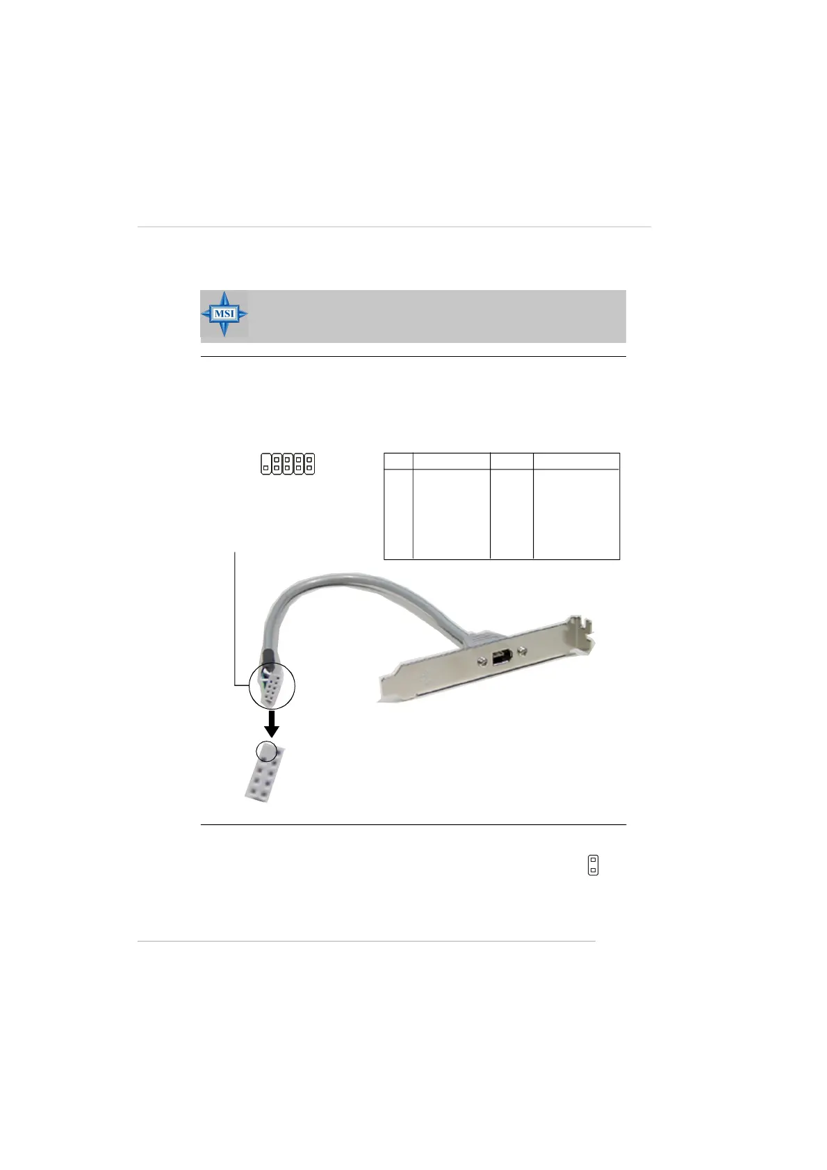
IEEE 1394 Connectors: J1394_1 (Optional)
The mainboard provides one 1394 pin header that allows you to connect IEEE
1394 ports via an external IEEE1394 bracket (optional).
Pin Definition
PIN SIGNAL PIN SIGNAL
1 TPA+ 2 TPA-
3 Ground 4 Ground
5 TPB+ 6 TPB-
7 Cable power 8 Cable power
9 Key (no pin) 10 Ground
Foolproof
design
Connected to J1394_1
IEEE1394 Bracket (Optional)
J1394_1
1
2
9
10
Chassis Intrusion Switch Connector: JCASE1
This connector is connected to a 2-pin chassis switch. If the
chassis is opened, the switch will be short. The system will record
this status and show a warning message on the screen. To clear
the warning, you must enter the BIOS utility and clear the record.
JCASE1
2
1
GND
CINTRU
 Loading...