COCKPIT SX M-LINK
MULTIPLEX Modellsport GmbH & Co.KG • Westliche Gewerbestraße 1 • D-75015 Bretten (Gölshausen) • www.multiplex-rc.de Page 26
12.5. Link Quality Indication (LQI)
12.5.1. Display of LQI value on the transmitter’s
integral screen
In addition to the receiver battery voltage, telemetry-
capable M-LINK receivers generate a value for recep-
tion quality (LQI = Link Quality Indication). No external
sensors need to be connected to the telemetry-capable
receiver in order to send these two values to the trans-
mitter.
The factory default setting for the LQI value display on
the C
OCKPIT SX M-LINK is INFO display 8, i.e. address 1
(Î 12.2.2.).
12.5.2. Definition of terms
a) “Transmitter” and “receiver”
Although the terms “transmitter” and “receiver” are no
longer technically precise (after all, telemetry-capable
transmitters and telemetry-capable receivers both
transmit and receive), this supplement continues to use
these two terms in their usual sense.
b) Uplink and downlink
Uplink, or “out” channel:
Î Connection from transmitter to receiver.
Downlink or “back” channel:
Î Connection from receiver to transmitter.
12.5.3. Indicated range of LQI values
The range of LQI values displayed on the transmitter’s
screen extends from
%
100 (best possible value) down
to
%
0 .
As the link quality declines - typically when the distance
between the model and the transmitter is increasing, or
when the model is in an unfavourable attitude - this
value diminishes in increments of 10%.
The LQI value shows the quality of the data trans-
mission from transmitter to receiver, i.e. it provides a
value for the quality of the uplink. The value is
calculated from the signal field strength and other
parameters. Since the field strength varies according to
the model’s attitude, and the model’s position is subject
to wide variations, the system automatically smoothes
out the value, taking further parameters into con-
sideration.
12.5.4. Interpreting the LQI value
a) General information
The sensitivity of the field strength measurement is
lower than the sensitivity of the M-LINK receiver itself.
This means that the receiver can certainly continue to
function even when the LQI value falls to
%
0 .
The transmitting power of the transmitter and receiver
is the same. Nevertheless the downlink channel - i.e.
the connection from the receiver to the transmitter -
breaks down earlier than the uplink channel. The
reason for this is the low sensitivity of the transmitter; it
is as if the transmitter were wearing “ear defenders”.
b) Normal operations
During normal operations (flying a model) the downlink
connection usually breaks down when the link quality
falls to an LQI value of about
%
60 . At this point the last
telemetry value assessed as valid is retained per-
manently on the transmitter screen, i.e. the screen
display “freezes”.
All the telemetry values are updated when the trans-
mitter picks up new data.
! Note:
If the downlink connection collapses at a value of
about
%
60 , for example, the connection with the
model (i.e. the uplink) continues to function.
c) Range check mode
When you select “range check” mode, the transmitted
power of the uplink channel is very greatly reduced
compared with the downlink channel (Î 3.2.). For this
reason the LQI display is an excellent means of
establishing the ideal orientation of the receiver
aerial(s) during the range check procedure:
A good method of optimising the aerial position in or on
the model is successively to alter the orientation of the
receiver aerial(s) whilst carrying out repeated range
checks, all the while observing the displayed LQI
values.
! Note:
The displayed LQI value may well show only
%
10 or
%
20 in range check mode, but the model will still be
under full control.
13. Setting up a new model
Model type: EASY
13.7.4. Model type EASY: changing the standard
assignment for receiver output 5 (aileron),
Menu: (MIXER) AI->S5
If you have set up a new model using the EASY model
type, then receiver output 5 is assigned to the second
aileron servo. If this is what you want, you do not need
to make any changes in this menu.
However, many model aircraft feature no ailerons at all,
or only require a single servo to operate both ailerons.
For such cases it is possible to assign receiver output
5 to other functions, if you wish.
You can control receiver output 5 using any of the
transmitter controls AI, EL, RU, TH, SP, F or the
switch PH.
This change can be carried out in the menu point
AI->S5 in the MIXER menu (see also Î
13.7.3.).
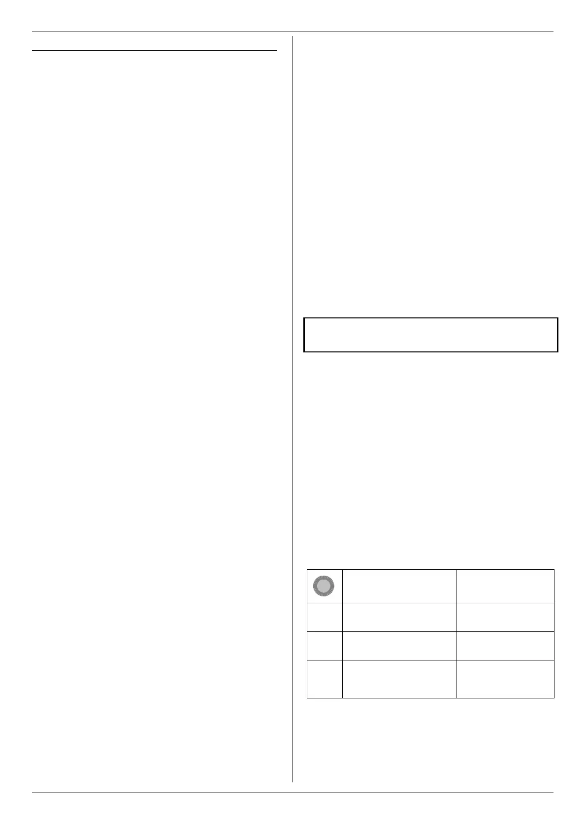
How to access the menu AI->S5:
Action Effect
1. 4
r
left to MENU
confirm SETUP appears
2. 3
r
right to MIXER
confirm TH->S4 appears
3. 3
r
right to
AI->S5
confirm
AI- flashes
By turning the rotary control (4 3) you can select the
switch or transmitter control to which you want to as-
sign receiver output 5:
 Loading...