2200LZJE-HO-C6-N_2013.12.
Chapter 5 Maintenance
Compound 2-stage Screw Compressor 2016**C 5.7 Reassembly
5-57
5.7.11 Low-stage Unloader Cylinder
The low-stage unloader cylinder may be attached immediately after attaching the bearing cover (see
"5.7.8 Bearing cover" in this manual), or after attaching the mechanical seal (see the description below).
The contents of and points for this work are almost the same as the previous section.
a) Fit the O-ring 【73-1】 in the O-ring groove at the end of the unloader push rod 【67-1】 where the
unloader piston is to be attached.
b) Attach the O-ring 【65】 and cap seal 【66】 to the unloader piston 【64-1】.
c) Attach the unloader piston, which has the O-ring and cap seal attached, to the unloader cylinder
【60-1】 (Photo 111).
d) Attach the O-ring to the O-ring groove provided on the portion of the bearing cover 【16】 where the
unloader cylinder is to be attached (Photo 112).
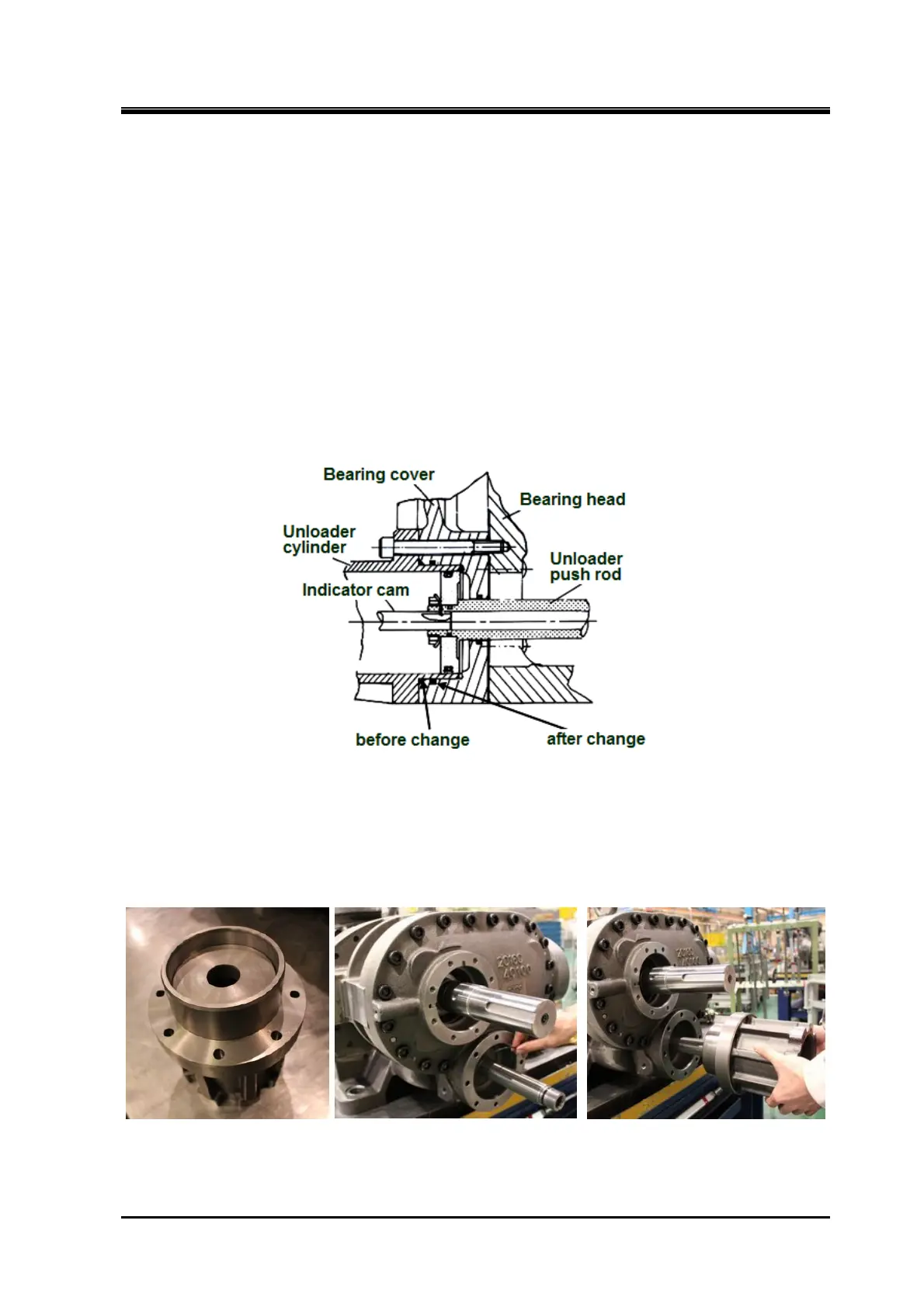
* According to the design change on October 1996, the place O-ring 【63】 is attached has been
changed from the opening with chamfered to the current position indicated in Figure 5-13.
Figure 5-13 Change of The O-ring position for Bearing cover
e) Attach the unloader cylinder to the bearing cover (Photo 114), and fasten the eight hexagon socket
head cap screws 【62-1】 to the specified torque (50 N·m).
Photo 111 Photo 112 Photo 113
 Loading...
