2200LZJE-HO-C6-N_2013.12.
Chapter 5 Maintenance
Compound 2-stage Screw Compressor 2016**C 5.6 Overhaul
5-18
5.6.2 Unloader Indicator
As the 2016**C model has a capacity control also on the high-stage side, it has two separately-placed
indicators. Normally, the low-stage capacity control only is used during operation. The high-stage
control capacity is used to reduce the startup load.
As various control methods are employed depending on the equipment, refer to the separate electrical
control wiring diagram (provided for each plant).
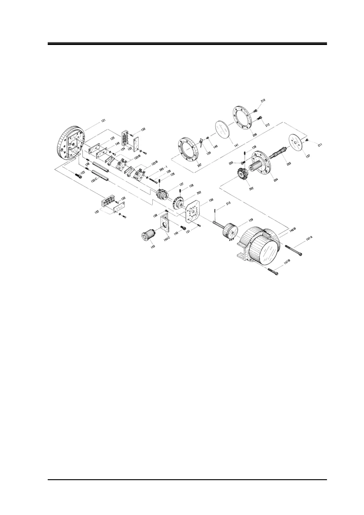
Figure 5-3 Development View of the 2016**C Standard-type Low-stage Indicator
5.6.2.1 Disassembly
When removing the compressor, the wiring of the unloader indicator has to be pulled out. As the
indicator has a terminal board for wiring, remove the cover from the indicator. Follow the procedure
below. After the wiring is removed, attach the cover again for protection.
○ Low-stage
a) Loosen the hexagon socket head cap screws 【212】 fastening the indicator glass 【141】. Do not by
mistake loosen the crosshead screw 【210】 on the same surface.
Remove assemblies‘ 【141】, 【202 to 207】, 【210】 and 【211】.
b) Remove hexagon socket head cap screws 【147A】 【147B】 (two each) that fasten the indicator
cover 【146B】. Then the cover gets removable.
c) There is a terminal block. Remove the plastic plate on the surface, and loosen the screws.
○ High-stage
a) Remove three hexagon socket head cap screws 【147】 that fasten the indicator cover 【146】. Then
the cover gets removable.
b) The indicator cover comes off with glass 【141】 and indicator glass spacer 【142】 attached. The
glass and the spacer are pasted together, however, take care not to drop them as they may come
apart.
c) Remove the wiring.
 Loading...
