2200LZJE-HO-C6-N_2013.12.
Chapter 3 Installation
Compound 2-stage Screw Compressor 2016**C 3.2 Installation Works
3-4
3.2.4 Preparation for Installation
Installation Space
Secure sufficient working space for easy operation, cleaning, maintenance, and inspection.
Illumination
Prepare illumination devices which allow easy operation, cleaning, maintenance, and inspection.
Ventilation
If natural ventilation is insufficient, install ventilation fans according to the relevant regulations.
Piping
Table 3-1 List of Connecting Pipes (Compressor)
Item Dimensions Remarks
Suction gas inlet JIS 20K 150A (6") See Figure 3-2.
Low-stage gas outlet JIS 20K 100A (4") See Figure 3-2.
High-stage gas inlet JIS 20K 100A (4") See Figure 3-2.
High-stage discharge gas outlet JIS 20K 80A (3") See Figure 3-2.
Lubrication oil supply port for low-stage
bearing (journal)
JIS 20K 25A (1")
Lubrication oil supply port for low-stage
capacity control (increased side)
Rc1/4
Lubrication oil supply port for low-stage
capacity control (decreased side)
Rc3/8
Oil supply port for oil injection
JIS 20K 15A (1/2")
Lubrication oil supply port for high-stage
bearing (journal)
JIS 20K 20A (3/4")
Lubrication oil supply port for high-stage
capacity control (increased side)
Rc3/8
Lubrication oil supply port for high-stage
capacity control (decreased side)
Rc1/4
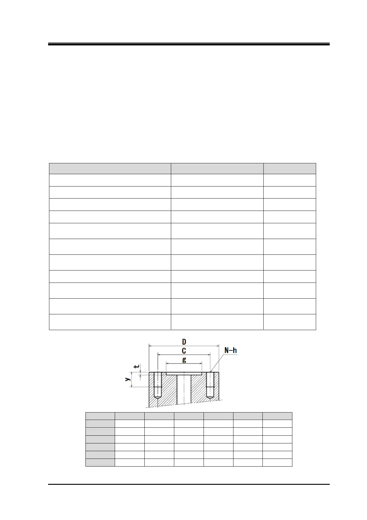
Figure 3-2 Dimensions of the Joint
D t g C N-h y
15A □ 74 5 43 70 4-M12 25
20A □ 84 5 51 75 4-M12 25
25A □100 5 61 90 4-M16 25
80A 200 5 121 160 8-M20 35
100A 225 5 146 185 8-M20 35
150A 305 5 216 260 12-M22 34
 Loading...
