2200LZJE-HO-C6-N_2013.12.
Chapter 2 Configuration and Specifications of Compressor
Compound 2-stage Screw Compressor 2016**C 2.3 Compressor Specifications
2-2
2.3 Compressor Specifications
2.3.1 Specifications
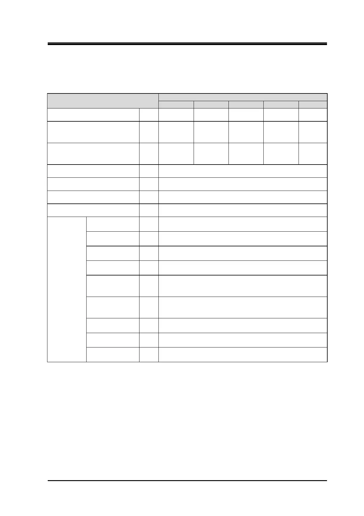
Table 2-1 2016**C Screw Compressor Specifications
Items
2016
LLC LMC LSC MSC SSC
Weight kg 1180 1140 1100 1050 1000
Low-stage theoretical
displacement
@3550 rpm /2950 rpm
m
3
/h 1460/1210 1460/1210 1460/1210 1220/1020 975/810
High-stage theoretical
displacement
@3550 rpm /2950 rpm
m
3
/h 749/622 624/519 499/415 499/415 499/415
Refrigerant - NH
3
, HFC, etc.
Design pressure MPa 2.6
Capacity control (Actual load) - 10 to 100%
Rotation direction - Counterclockwise viewed from motor
Connected
pipe size
Low-stage
suction flange
- JIS 20K 150A (6")
Low-stage
discharge flange
- JIS 20K 100A (4")
High-stage
suction flange
- JIS 20K 100A (4")
High-stage
discharge flange
- JIS 20K 80A (3")
Journal
lubrication
(low-stage)
- JIS 20K 25A (1")
Journal
lubrication
(high-stage)
- JIS 20K 20A (3/4")
Oil injection
lubrication
- JIS 20K 15A (1/2")
Low-stage
capacity control
- Load: Rc1/4, Unload: Rc3/8
High-stage
capacity control
- Load: Rc3/8, Unload: Rc1/4
Unless otherwise noted, the pressure unit MPa represents the gauge pressure
in this manual.
For limits of working temperature and pressure, see "2.3.2 Operation Limits" in
this manual.
 Loading...
