2200LZJE-HO-C6-N_2013.12.
Chapter 7 Related Documents
Compound 2-stage Screw Compressor 2016**C 7.3 Tightening Torques for Bolts and Nuts
7-21
Lock Nut
No. What is tightened
Tightening torque (N·m)
Q’ty. Size
Standard Maximum
39-1 Thrust Bearing (1) Note 1 522 653 2 AN13
39-2 Thrust Bearing (2) Note 1 408 510 2 AN12
69-1 Unloader Piston (1) * Specified torque 120 - 1 AN07
69-2 Unloader Piston (2) * Specified torque 80 - 1 AN05
71-1 Unloader Slide Valve (1-1) 79 99 1 AN07
71-2 Unloader Slide Valve (1-2) 28 35 1 AN05
160 Gear Coupling Drive Hub Note 1 238 297 1 AN10
Note 1: On June 14, 2010, the "Lock Nut Tightening Angle Range Control Standard" has been
introduced to our compressor manufacturing division, to control the specified tightening
torque for rotor shaft lock nuts (【39-1】【39-2】【160】 in tables above) as follows. Accordingly,
the tightening angle range is now added to the rotor shaft lock nut tightening procedure in this
manual.
Tightening Angle Range of Lock Nuts for Rotors
a) After tightening the lock nut by hand, further tighten the lock nut by using a lock nut wrench until the
rotor starts to turn. Take care not to over-tighten.
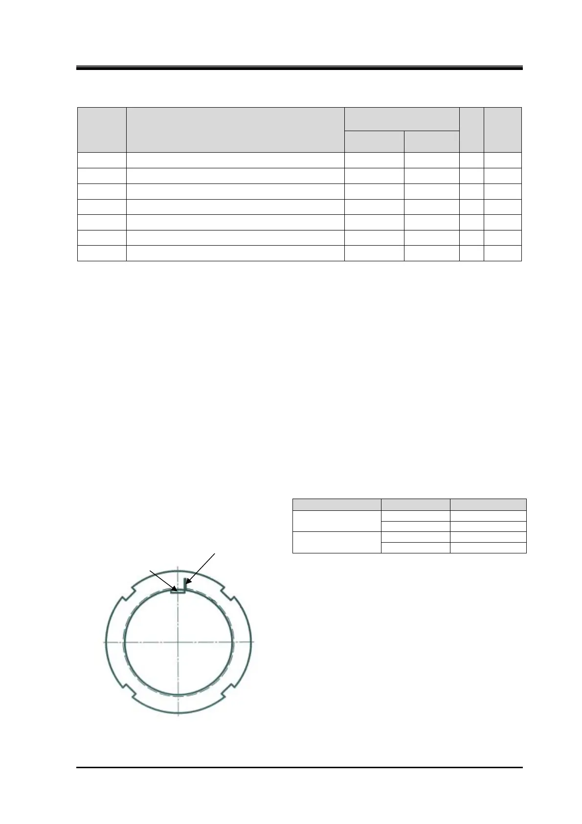
b) Put a mark on the lock nut at the right side edge of the rotor groove where the stopper tongue of the
lock washer fits in, as shown in Figure 7-9.
c) From this marking position, tighten the lock nut in such a way that rotation can be stopped within the
tightening angle range shown in Table 7-3 (2016**C【39-1】,【39-2】and【160】: 30° to 40°(first time
tightening), 20° to 30°(second time tightening). When measuring the angle, use an angle gauge
which is set to the diameter of rotor shaft.
Table 7-3 Tightening Angles Specified
for Lock Nuts of Rotor
* When tightening lock nut, tightening start position
differs between the first time tightening and the
tightening for the second time or after. Therefore,
angle ranges are specified also for the second
time tightening.
Figure 7-9 Position where mark is put
Model Angle range
First time
tightening
125 to 250 30°to 40°
320/400 25°to 35°
Second time
tightening
125 to 250 20°to 30°
320/400 15°to 25°
Marking
Rotor groove (slot)
where stopper tongue of
the lock washer fits
 Loading...
