7-24 | ni.com
Chapter 7 Counters
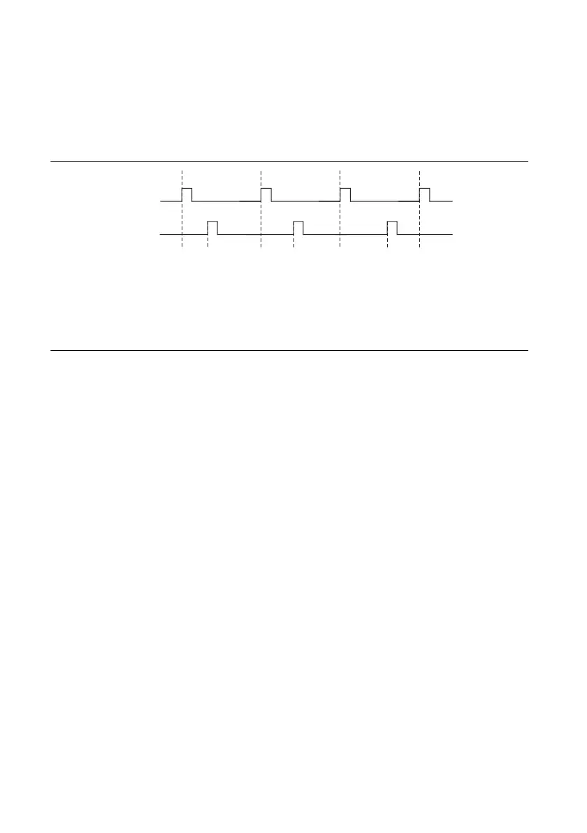
The waveform thus produced at the counter’s output can be used to provide timing for
undersampling applications where a digitizing system can sample repetitive waveforms that are
higher in frequency than the Nyquist frequency of the system. Figure 7-29 shows an example of
pulse generation for ETS; the delay from the trigger to the pulse increases after each subsequent
Gate active edge.
Figure 7-29. Pulse Generation for ETS
For information about connecting counter signals, refer to the
Default Counter/Timer Pinouts
section.
Counter Timing Signals
M Series devices feature the following counter timing signals:
•
Counter n Source Signal
• Counter n Gate Signal
• Counter n Aux Signal
• Counter n A Signal
• Counter n B Signal
• Counter n Z Signal
• Counter n Up_Down Signal
• Counter n HW Arm Signal
• Counter n Internal Output Signal
• Counter n TC Signal
• Frequency Output Signal
In this section, n refers to either Counter 0 or 1. For example, Counter n Source refers to
two signals—Counter 0 Source (the source input to Counter 0) and Counter 1 Source (the source
input to Counter 1).
Counter
n Source Signal
The selected edge of the Counter n Source signal increments and decrements the counter value
depending on the application the counter is performing. Table 7-5 lists how this terminal is used
in various applications.
OUT
D1 D2 = D1 + ΔDD3 = D1 + 2ΔD
GATE

 Loading...


