© National Instruments | 5-5
M Series User Manual
• Non-buffered—In non-buffered acquisitions, data is written directly to the DACs on the
device. Typically, hardware-timed, non-buffered operations are used to write single
samples with good latency and known time increments between them.
Note (NI USB-62
xx Devices) USB M Series devices do not support non-buffered
hardware-timed operations.
Analog Output Triggering
Analog output supports two different triggering actions:
• Start trigger
• Pause trigger
An analog or digital trigger can initiate these actions. All M Series devices support digital
triggering, but some do not support analog triggering. To find your device’s triggering options,
refer to the specifications document for your device. Refer to the
AO Start Trigger Signal and
AO Pause Trigger Signal sections for more information about these triggering actions.
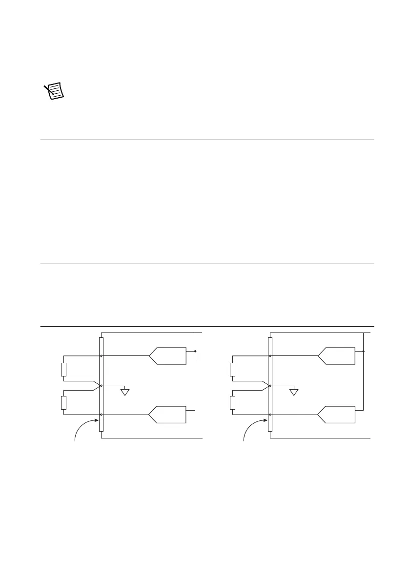
Connecting Analog Output Signals
AO <0..3> are the voltage output signals for AO channels 0, 1, 2, and 3. AO GND is the ground
reference for AO <0..3>.
Figure 5-2 shows how to make AO connections to the device.
Figure 5-2. Analog Output Connections
Load
Load
V OUT
V OUT
+
–
+
–
AO GND
AO 3
Analog Output Channels
AO 2
Channel 3
Connector 1 (AI 16–31)
Channel 2
M Series Device
Load
Load
V OUT
V OUT
+
–
+
–
AO GND
AO 1
Analog Output Channels
M Series Device
AO 0
Channel 1
Channel 0
Connector 0 (AI 0 –15)

 Loading...


