© National Instruments | 4-21
M Series User Manual
Field Wiring Considerations
Environmental noise can seriously affect the measurement accuracy of the device if you do not
take proper care when running signal wires between signal sources and the device. The
following recommendations apply mainly to AI signal routing to the device, although they also
apply to signal routing in general.
Minimize noise pickup and maximize measurement accuracy by taking the following
precautions:
• Use DIFF AI connections to reject common-mode noise.
• Use individually shielded, twisted-pair wires to connect AI signals to the device. With this
type of wire, the signals attached to the positive and negative input channels are twisted
together and then covered with a shield. You then connect this shield only at one point to
the signal source ground. This kind of connection is required for signals traveling through
areas with large magnetic fields or high electromagnetic interference.
Refer to the Field Wiring and Noise Considerations for Analog Signals document for more
information. To access this document, go to
ni.com/info and enter the Info Code rdfwn3.
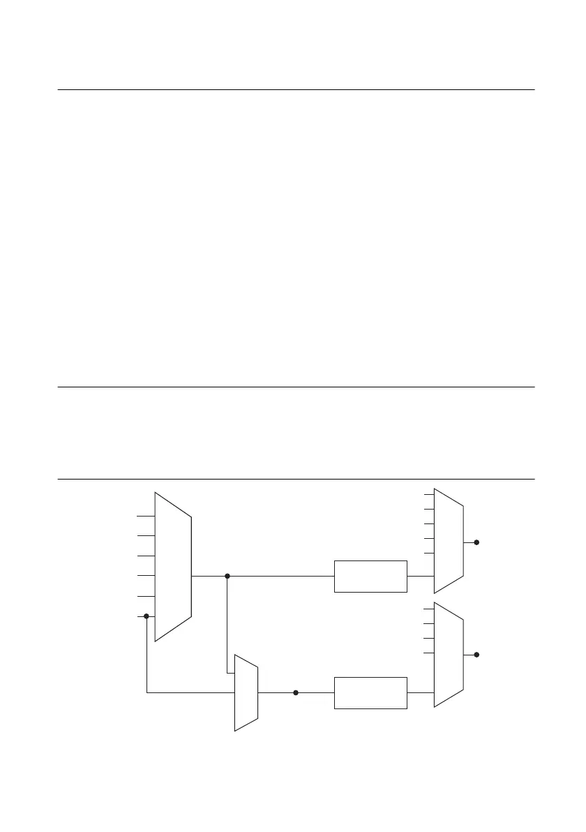
Analog Input Timing Signals
In order to provide all of the timing functionality described throughout this section, M Series
devices have a flexible timing engine. Figure 4-12 summarizes all of the timing options provided
by the analog input timing engine. Also refer to the
Clock Routing section of Chapter 9, Digital
Routing and Clock Generation.
Figure 4-12. Analog Input Timing Options
PFI, RTSI
PXI_STA R
Analog Comparison
Event
20 MHz Timebase
100 kHz Timebase
PXI_CLK10
Programmable
Clock
Divider
Programmable
Clock
Divider
AI Sample Clock
Timebase
AI Convert Clock
Timebase
PFI, RTSI
PXI_STA R
Analog Comparison Event
Ctr
n Internal Output
SW Pulse
PFI, RTSI
PXI_STA R
Analog Comparison Event
Ctr
n Internal Output
AI Convert Clock
AI Sample Clock

 Loading...


