NI Digital System Development Board User Manual | © National Instruments | 17
The signals from the NI ELVIS edge connector are routed to the Power breadboard header, the
NI ELVIS Analog breadboard header, and the programmable logic of the Zynq. The connections
are described in Tables 4 and 5 below. NI ELVIS pins not listed in the tables below are not
connected to any device on the DSDB. Note that +5 V from this connector is also used to power
the entire board. The GND pins of the NI ELVIS connector, the ground plane of the DSDB, and
the pins labeled GND on the breadboard headers are all connected. For further information on
the functionality of the pins on the NI ELVIS connector, please refer to the NI ELVIS
documentation.
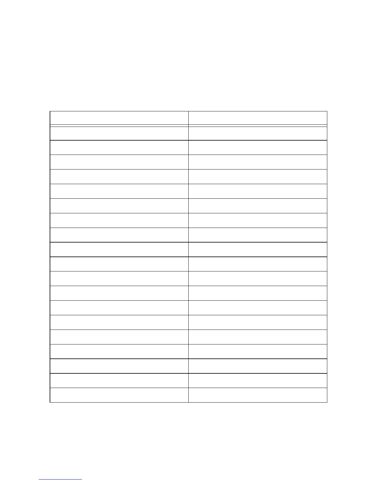
Table 4. NI ELVIS breadboard connections
NI ELVIS Pin Zynq Pin
DIO0 Y20
DIO1 AA16
DIO2 Y19
DIO3 AB16
DIO4 AA18
DIO5 AB15
DIO6 Y18
DIO7 AA14
DIO8 T19
DIO9 AA19
DIO10 U20
DIO11 AB19
DIO12 U10
DIO13 AA17
DIO14 W20
DIO15 AB17
PFI8 N19
PFI9 AB20
PFI12 R21
 Loading...