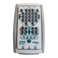
User and Service Manual XLTEK EEG32U Amplifier
33
2. Start XLTEK Database (XLDB).
3. To start a new study, click New.
4. Choose Edit > Settings > Acquisition.
5. In the Acquisition tab, set the Reference Electrode to Common.
6. Design a bipolar montage using pairs of the channels to be verified. For example, to verify C3, C4, O1 and O2, use a
montage with C3-C4 and O1-O2.
7. Apply a sine wave of 50 microvolts, peak-to-peak amplitude, 10 Hz to all channels of the group using a signal
generator. Ensure that there is a 50 Ohm load on the generator output if the generator is designed to deliver the
specified level into this load.
8. Set the LFF filter to 0.1, the HFF filter to OFF, and the Notch filter to OFF.
9. Verify that no sine wave is greater than 50 microvolts peak-to-peak. The accuracy of the gain is +/- 1%.
NOTE: For more information on setting up a montage, consult the online Help.
Channel Test
While you are working in the NeuroWorks live recording screen, a channel test may be performed to verify the integrity of the
signal processing from the amplifier input through to the display. A channel test applies a test signal to all channels. This allows
you to examine the waveforms on the screen to see if all the channels are functioning.
NOTE: A channel test does not validate the connection from the patient electrode to the amplifier input.
To Run a Channel Test
1. In NeuroWorks EEG, choose Edit > Settings. The Edit Settings box appears.
2. To open the Acquisition dialog box, click the Acquisition tab.
3. Select Common in the Reference Electrode list box and click OK.
4. Choose Controls > Channel Test Signal. The Channel Test control bar appears above the waveform window.
5. Use the Channel Test toolbar to select the desired wave shape, amplitude, and frequency.
6. To stop the channel test, click Done.
Channel Test Signal Control
The Channel Test Signal control in NeuroWorks EEG turns on the channel test signal according to the last settings saved and
displays the Channel Test Signal toolbar. The toolbar has controls for shape, amplitude and frequency.
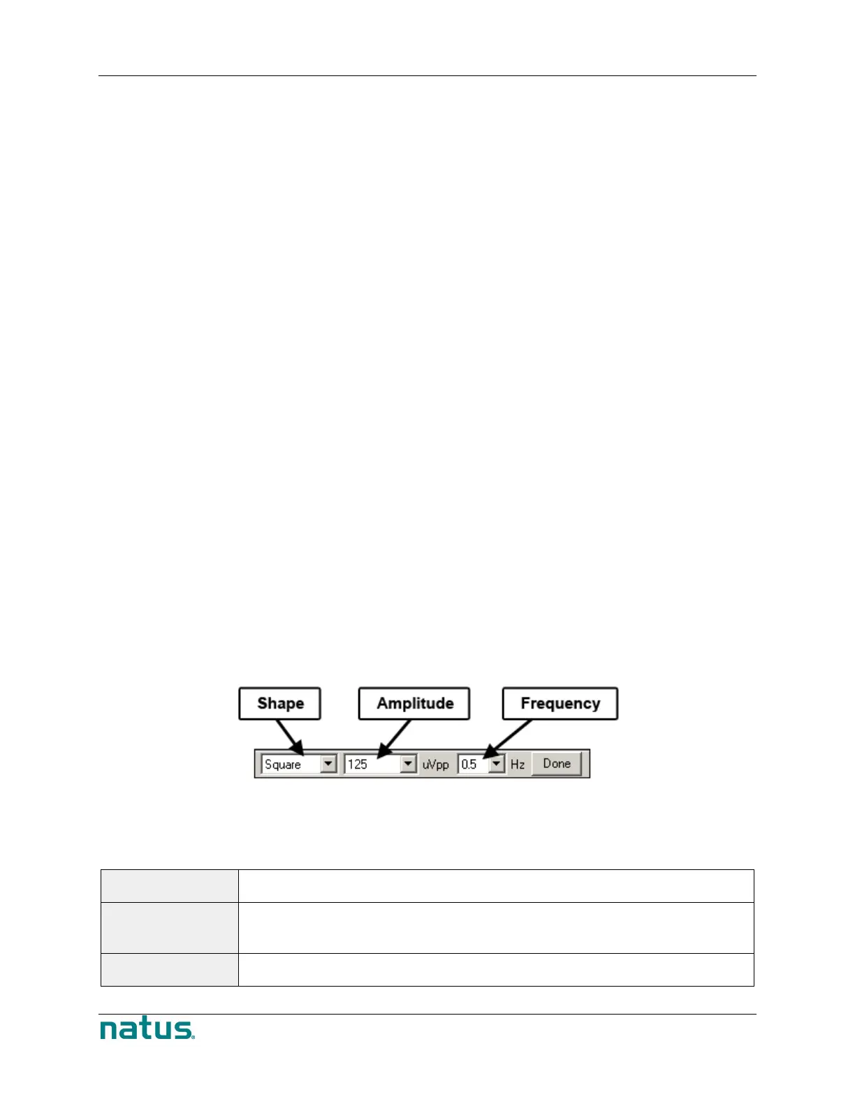
Channel Test Signal Toolbar
Available Channel Test Signal Settings
Shape Sine or Square
Amplitude Sine wave amplitude can be 79, 158, 316, 632, 1264, 2527.5, 5055 and 10110 µV peak to peak.
Square wave amplitude can be 50, 100, 200, 400, 800, 1600, 3200, and 6400 µV peak to peak.
Frequency Sine wave frequency can be 16, 32 or 64 Hz. Square wave frequency can be 0.25, 0.5 or 1 Hz
 Loading...