XLTEK EEG32U Amplifier User and Service Manual
40
Theory of Operation:
Introduction
This section describes the theory of operation of the 32 channel EEG amplifier. The initial discussion is primarily signal flow
oriented. Detailed board level theory is provided later in this section.
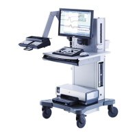
System Overview
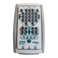
Features of the EEG32U Amplifier System
The EEG32U amplifier performs these basic functions of a digital EEG front end:
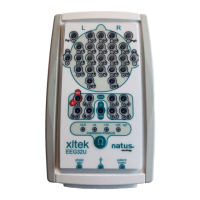
• Allows connecting patient electrodes.
• Amplifies and digitizes the electrode signals.
• Transmits the digitized waveforms to a NeuroWorks computer.
• Allows selection of reference signal.
• Provides internally generated test signals (sine and square) for user assessment of equipment performance.
Components of the Communications Link
• Digitized waveforms are transmitted to the computer using USB (universal serial bus) connection.
• Commands and replies are communicated using same USB (universal serial bus) connection.
Power Sources to the Amplifier
• Power to EEG32U amplifier is supplied by a USB bus.
Circuit Board Assemblies inside the Amplifier
A. Analog Board
• Handles amplification and DC removal (DC removal is like a low frequency filter) for 32 channels.
• Amplifiers are designed to handle signals far more than even abnormally high EEG, while also providing exceptional
sensitivity and resolution.
B. Digital Board
• Analog to Digital converters digitize the amplified EEG signals. Signals are periodically sampled and converted to a
binary number.
• The micro controller transmits the digitized signals to the computer over USB 2.0 connection.
• Contains non-volatile storage for calibration values.
• During factory calibration, the NeuroWorks computer calculates and transmits the channels gains to each digital
board. Whenever a study starts, the computer uses these stored values to scale the digitized signals, channel by
channel.
• Equipped with a Patient Event connector that detects an Event Switch closure and transmits it to the computer.
• Equipped with a Photic stimulator connector that allows to:
• Transmit commands from the computer to the photic stimulator over USB 2.0 connection.
• Transmit feedback (flash strobe marks) from the photic stimulator to the computer over USB 2.0 connection.
 Loading...