CONNECTING THE BRINE SIDE
• Insulate all indoor brine pipes against condensation.
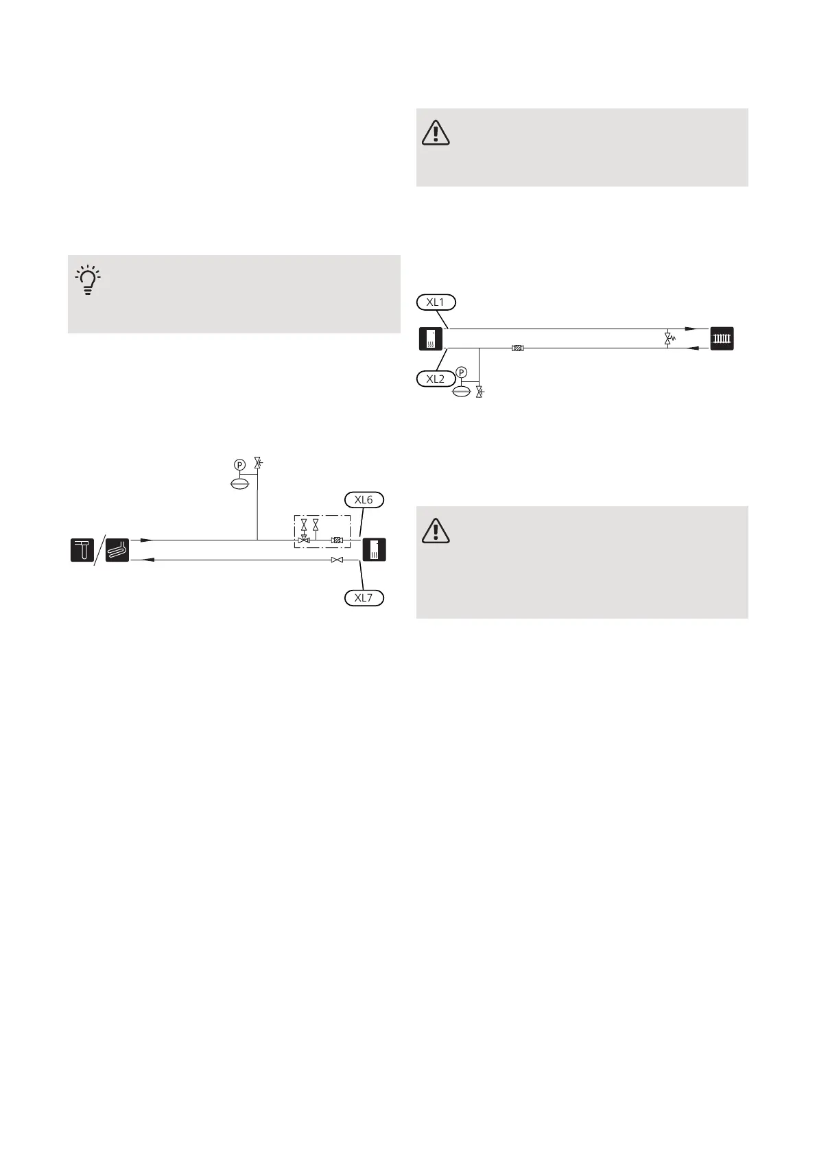
• The system must be fitted with an expansion vessel
(CM3), pressure gauge (BP6) and the enclosed safety
valve (FL3).
• Install a shut off valve for outgoing brine as close to
the heat pump as possible.
• Fit the enclosed filterball on the incoming brine.
TIP
If filling connection KB25/KB32 is used, the
enclosed filterball does not need to be fitted.
In the case of connection to an open groundwater sys-
tem, an intermediate frost-protected circuit must be
provided, because of the risk of dirt and freezing in the
evaporator. This requires an extra heat exchanger.
Heating medium side
CONNECTING THE CLIMATE SYSTEM
A climate system is a system that regulates indoor
comfort with the help of the control system in F1155
and for example radiators, underfloor heating/cooling,
fan convectors etc.
• Install all necessary safety devices, shut-off valves (as
close to the heat pump as possible) and the enclosed
filterball.
• Fit safety valve on heating medium return as illus-
trated. Recommended opening pressure is 0.25 MPa
(2.5 bar). For information about max opening pressure,
see technical specifications.
• When connecting to a system with thermostats on all
radiators (or underfloor heating coils), either a bypass
valve must be fitted or some of the thermostats must
be removed to ensure there is sufficient flow.
Before installing the heat pump in an existing system,
it is important that the system is properly flushed
through.
Even if the heat pump is to be installed in a new system,
the heat pump and system should be flushed.
NOTE
Ensure that cleaning agent has been removed
from the entire system before adding inhibitor.
After flushing an inhibitor should be used for long-term
anti-corrosion protection.
NIBE Energy Systems Limited recommends water
treatments (supplied by e.g. Fernox and Sentinel) spe-
cifically designed for heat pumps.
Cold and hot water
CONNECTING THE HOT WATER HEATER
NOTE
If F1155 is not docked to a water heater or if
it is to work with fixed condensing, the connec-
tion for the water heater (XL9) must be
plugged.
• Fit shut-off valve, non-return valve, expansion relief
valve, pressure reduction valve, expansion vessel and
tundish as illustrated.
• The expansion relief valve must have a maximum 0.6
MPa (6.0 bar) opening pressure and be installed on
the incoming domestic water line as shown.
• The expansion vessel (CM4) accomodates expansion
that results from heating the water inside the unit.
The expansion vessel must be connected between
the expansion releif valve (FL1) and the water heater.
The location of the expansion vessel should allow ac-
cess to recharge the pressure as and when nec-
cessary.
• Stop temperature for hot water must be at least 60°C.
• A mixing valve must be installed when the factory
setting for hot water is changed. National regulations
must be observed.
• Hot water production is activated in the start guide or
in menu 5.2.
17Chapter 4 | Pipe connectionsNIBE F1155
 Loading...


