• hot water (hot water production). Any hot water circu-
lation (HWC) remains in operation.
• compressor
• internally controlled additional heat
• tariff blocking (additional heat, compressor, heating,
cooling and hot water are disconnected)
POSSIBLE SELECTION FOR AUX OUTPUT
(POTENTIAL FREE VARIABLE RELAY)
It is possible to have an external connection through the
relay function via a potential free variable relay (max 2
A) on the input circuit board (AA3), terminal block X7.
Optional functions for external connection:
• Indication of buzzer alarm.
• Controlling ground water pump.
• Cooling mode indication (only applies if cooling ac-
cessories are available).
• Control of circulation pump for hot water circulation.
• External circulation pump (for heating medium).
• External, reversing valve for hot water.
• Holiday indication.
If any of the above is installed to terminal block X7 it
must be selected in menu 5.4, see page 53.
The common alarm is preselected at the factory.
NOTE
An accessory card is required if several func-
tions are connected to terminal block X7 at the
same time that the buzzer alarm is activated
(see page 65).
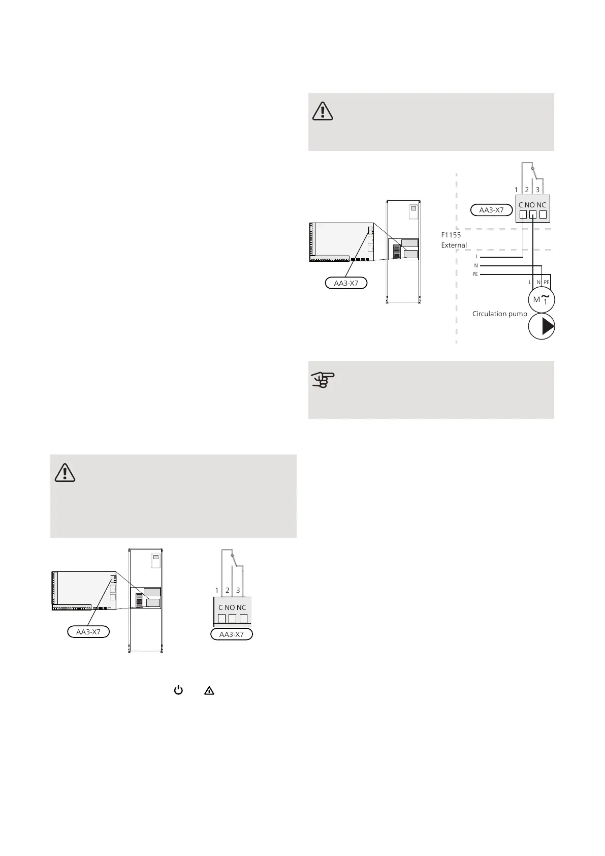
The picture shows the relay in the alarm position.
When switch (SF1) is in the " " or “ ” position the relay
is in the alarm position.
External circulation pump, ground water pump or hot
water circulation pump connected to the buzzer alarm
relay as illustrated below.
NOTE
Mark up any junction boxes with warnings for
external voltage.
AA3-X7
C NO NC
1 2 3
External
F1155
Circulation pump
Caution
The relay outputs can have a max load of 2 A
(230V ~).
Connecting
accessories
Instructions for connecting accessories are in the install-
ation instructions provided for the respective accessory.
See information at nibe.co.uk for the list of the accessor-
ies that can be used with F1155.
ACCESSORIES WITH CIRCUIT BOARD AA5
Accessories that contain circuit board AA5 are connected
to the heat pump terminal block AA3-X4: 13-15. Use
cable type LiYY, EKKX or similar.
If several accessories are to be connected, connect the
first accessory card directly to the heat pump terminal
block. Other accessory boards are connected to the first
in series.
Because there can be different connections for accessor-
ies with circuit boards AA5, you should always read the
instructions in the manual for the accessory that you
are going to install.
NIBE F1155Chapter 5 | Electrical connections28
 Loading...


