3.
Pull off the cover.
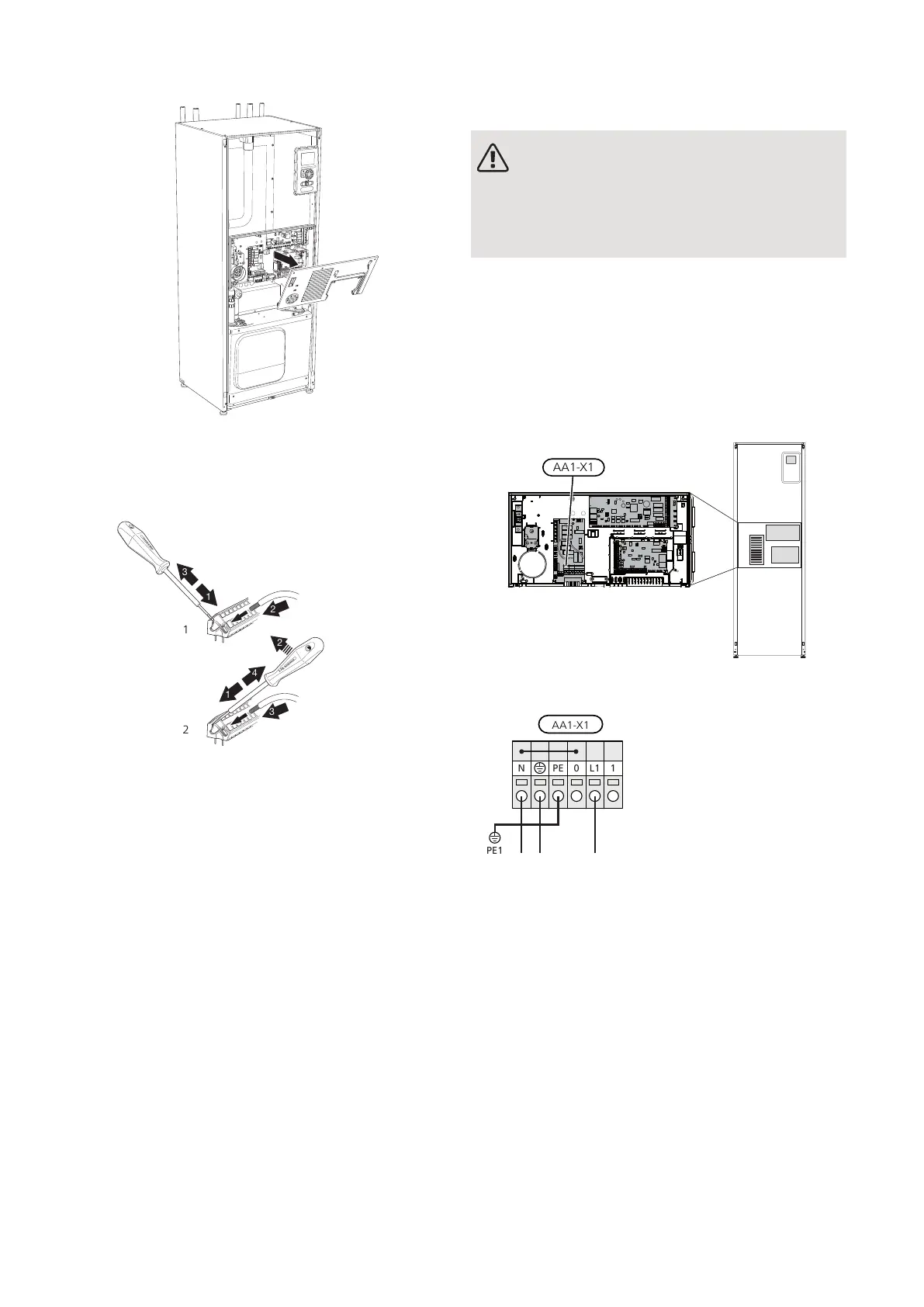
CABLE LOCK
Use a suitable tool to release/lock cables in the heat
pump terminal blocks.
Connections
NOTE
To prevent interference, unscreened commu-
nication and/or sensor to external connections
cables must not be laid closer than 20 cm to
high voltage cable when cable routing.
POWER CONNECTION
F1155 must be installed with a disconnection option on
the supply cable. Minimum cable area must be sized
according to the fuse rating used. Enclosed cable for
incoming supply electricity is connected to terminal block
X1 on the immersion heater board (AA1). All installations
must be carried out in accordance with current norms
and directives.
Connection 1x230V
If a separate supply to the compressor and electric
heater is wanted, see section "External blocking of
functions" on page 28.
TARIFF CONTROL
If the voltage to the immersion heater and/or the com-
pressor disappears during a certain period, there must
also be blocking via the AUX-input, see "Connection
options - Possible selection for AUX inputs" page. 28
NIBE F1155Chapter 5 | Electrical connections22
 Loading...


