General
BT7
QN10
BT2
EB1
PZ1
QM34
QM31
BT6
QM32
QM33
PZ2
QM22
UB1
AA4
SF1
AA4-XF3
XL1
XL6
XL4 XL3
XL7
XL2
BF1
UB2
FC1
XL5
XF8
FR1
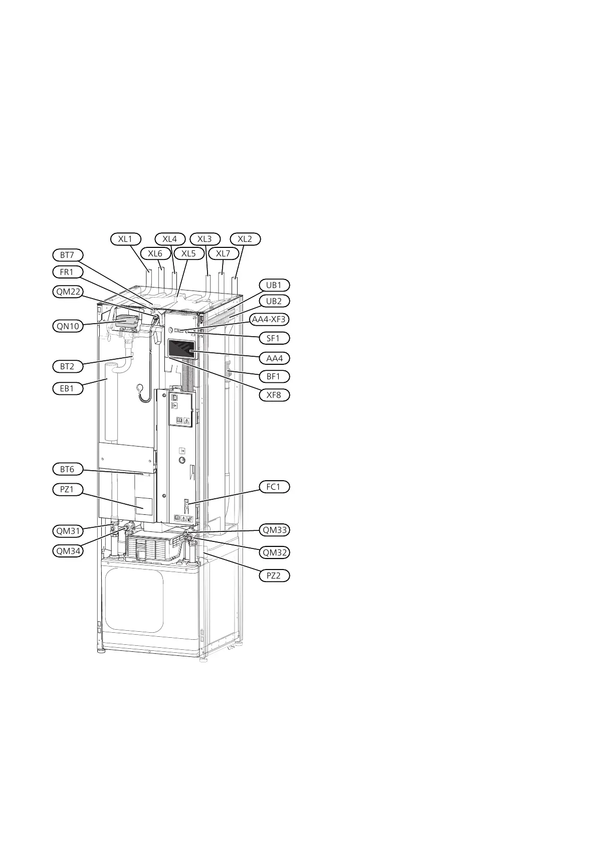
PIPE CONNECTIONS
Connection, heating medium flowXL1
Connection, heating medium returnXL2
Connection, cold waterXL3
Connection, hot waterXL4
Connection, HWC
1
XL5
Connection, brine inXL6
Connection, brine outXL7
1
Only heat pumps with enamelled or stainless steel vessel.
HVAC COMPONENTS
Venting, coilQM22
Shut-off valve, heating medium flowQM31
Shut off valve, heating medium returnQM32
Shut off valve, brine outQM33
Shut-off valve, brine inQM34
Shuttle valve, climate system/water heaterQN10
SENSORS ETC.
Flow meterBF1
Temperature sensors, heating medium flowBT2
Temperature sensor, hot water chargingBT6
Temperature sensor, hot water topBT7
ELECTRICAL COMPONENTS
Display unitAA4
AA4-XF3 USB port
Immersion heaterEB1
Miniature circuit breaker
1
FC1
Electrical anode
2
FR1
On/off buttonSF1
Network connection for myUplinkXF8
1
S1255-6 3x400 V is not equipped with miniature circuit breakers
(FC1).
2
Only heat pump with enamelled vessel.
MISCELLANEOUS
Rating platePZ1
Identification plate, cooling modulePZ2
Cable glandUB1
Cable glandUB2
Designations according to standard EN 81346-2.
NIBE S1255Chapter 3 | The heat pump design10
3 The heat pump design
 Loading...