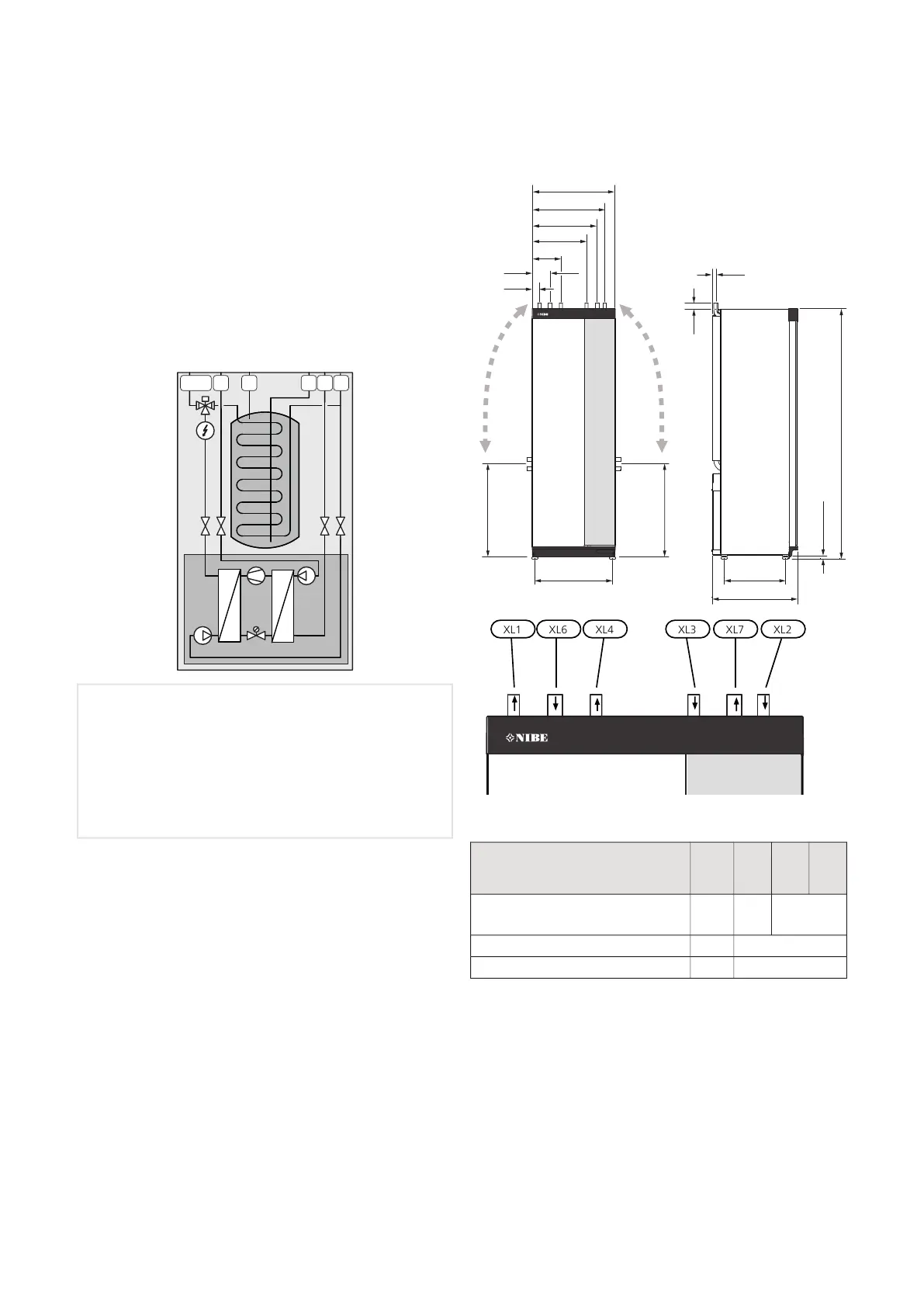
SYSTEM DIAGRAM
S1255 consists of a heat pump, water heater, electrical
module, circulation pumps and a control system. S1255
is connected to the brine and heating medium circuits.
In the heat pump evaporator, the brine (water mixed
with anti-freeze, glycol or ethanol) releases its energy
to the refrigerant, which is vaporised in order to be
compressed in the compressor. The refrigerant, of which
the temperature has now been raised, is passed to the
condenser where it gives off its energy to the heating
medium circuit and, if necessary, to the water heater.
If there is a greater need for heating/hot water than the
compressor can provide there is an integrated immersion
heater.
Connection, heating medium flowXL1
Connection, heating medium returnXL2
Connection, cold waterXL3
Connection, hot waterXL4
Connection, brine inXL6
Connection, brine outXL7
Dimensions and pipe
connections
560 440
70
1800
650*
20-50
650*
600
60
135
210
390
465
540
25
622
622
600
560 440
70
1800
650*
20-50
25
60
135
210
390
465
540
650*
PIPE DIMENSIONS
16
kW
12
kW
6
kW
Connection
2822(mm)(XL1)/(XL2) Heating medium
supply/return ext. Ø
22(mm)(XL3)/(XL4) Cold/hot water Ø
28(mm)(XL6)/(XL7) Brine in/out ext. Ø
* Can be angled for side connection.
NIBE S1255Chapter 4 | Pipe connections14
 Loading...