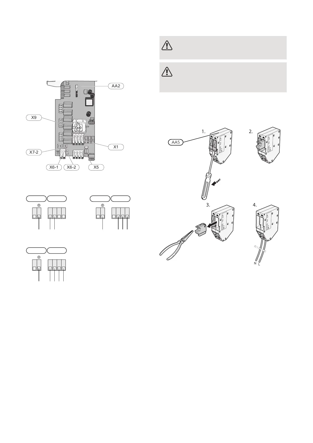
Connections
POWER CONNECTION
Supply voltage
Enclosed cable for incoming supply electricity is connec-
ted to terminal block X1 and X6-1 on the PCB AA2.
-X29
-X28
1 0-5V
2 +5V
3 AUX1
4 AUX2
5 AUX3
6 AUX4
7 AUX5
8 AUX6
9 AUX7
10 AUX8
11 AUX9
12 BT25
1
1
2
3
2
3
4
5
6
7
8
9
10
11
12
GND
+12V
B
A
OT+
OT−
0-5V
PWM0
PWM1
CPU
EXT COM
INT COM
ERROR
POWER
+5V
GND
BE1
BE2
BE3
K10
-X27
NO
O
NC
AUX-RELAY
13 BT50
14 BT1
-X30
X29
X28 X27
AA2
X9
X7-2
X6-1 X6-2 X5
X1
X30
Connection 3x230V
AA2-X1
PE (L2) L1 L2 L3
1 2 3 4
AA2-X6-1
Connection 1x230V
AA2-X1
PE N L (L) (L)
1 2 3 4
AA2-X6-1
Connection 3x400V
AA2-X1
AA2-X6-1
PE N L1 L2 L3
1 2 3 4
If separate supply to the compressor and electric heater
is required, see section "External blocking of functions".
Tariff control
If the voltage to the immersion heater and/or com-
pressor is lost for a period, this must be blocked at the
same time via the selectable inputs, see section "Select-
able inputs/outputs – Possible selections for AUX inputs".
External control voltage for the control system
NOTE
Only applies to power connection 3x400 V.
NOTE
Mark up any junction boxes with warnings for
external voltage.
Control voltage (230 V ~ 50Hz) connects to AA2:X5:N,
X5:L and X6-2 (PE).
When connecting external control voltage, remove the
bridges from terminal block X5.
NIBE S1255Chapter 5 | Electrical connections20
 Loading...