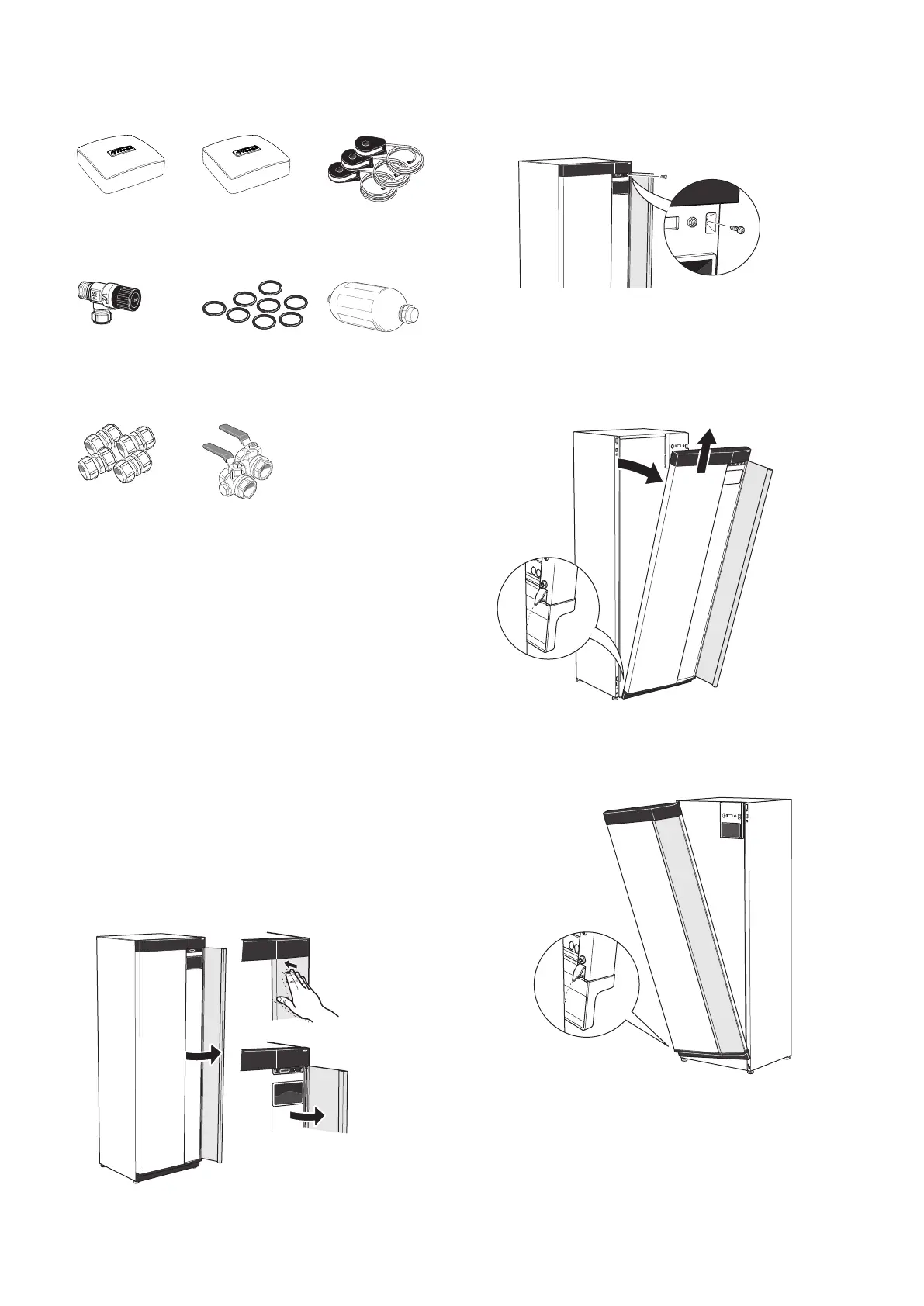
Supplied components
Current sensor
1
3 x
Room sensor
1 x
Outside sensor
1 x
Level vessel
1
1 x
O-rings
8 x
Safety valve
0.3 MPa (3 bar)
1
1 x
Filterball
6 kW
1 x G1
1 x G3/4
12/16 kW
1 x G1
1 x G1 1/4
Compression ring
couplings
6 kW
2 x (ø28 x G25)
2 x (ø22 x G20)
12/16 kW
4 x (ø28 x G25)
1
Not Italy and the DACH countries.
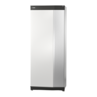
LOCATION
The kit of supplied items is placed in packaging on top
of the heat pump.
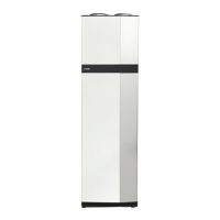
Handling panels
OPEN FRONT HATCH
Press the hatch's top left corner to open it.
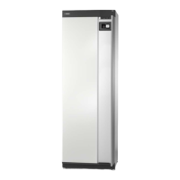
REMOVE THE FRONT
1.
Remove the screw in the hole next to the on/off
button (SF1).
2.
Pull the panel's top edge towards you and lift diag-
onally upwards to remove it from the frame.
ASSEMBLE THE FRONT
1.
Hook one bottom corner of the front onto the frame.
7Chapter 2 | Delivery and handlingNIBE S1255
 Loading...