23 – English
English
FURTHER INFORMATION
A - OTHER TASKS REGARDING
INSTALLATION AND CONNECTIONS
Some installation and/or connection tasks require removal of the control
unit and/or power supply unit.
The control unit needs to be removed when the following is required;
• control unit replacement (paragraph A.1);
• power cable replacement (paragraph 8.1.1);
• connection of SOLEKIT photovoltaic power supply (paragraph A.5);
• adjustment of gearmotor feet (paragraph 5.4);
• insertion and connection of PR200 battery (paragraph A.4).
The power supply unit needs to be removed when the following is
required;
• power supply unit replacement (paragraph A.2);
• power cable replacement (paragraph 8.1.1);
• rotation of xing bracket behind gearmotor (g. 21);
• power supply unit fuse replacement (paragraph A.3).
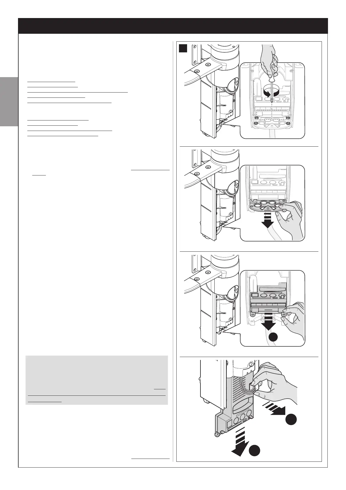
A.1 - Removing the control unit
01. Remove the lower cover of the gearmotor as shown in g. 22;
02. Then, with reference to g. 32, use a Phillips screwdriver to loosen
the 4 cable ducting support scres, and remove;
03. Pull the control unit in the direction of the arrow, by approx. 4 centi-
metres, and detach the motor connector;
04. Then remove the control unit completely.
Caution! - hen the control unit is retted, insert the motor con-
nector again on the control unit, taking care to observe polarity
(the connector can only be tted in one direction).
A.2 - Removing the power supply unit
The power supply unit is located on the upper section of the gearmotor.
To remove, proceed as follows.
01. With reference to g. 33, loosen the 3 screws of the upper cover of
the gearmotor and slowly turn the cover in the direction of the arrow
(take care to avoid the wires below!);
02. Remove the connector with 5-wire plate (C), pulling it in the direction
of the arrow;
03. Lastly, loosen the screws of the power terminal (D) and withdraw the
3 wires.
Caution! - hen the connector ith 5-ire plate is retted, take
care to observe polarity (the connector can only be tted in one
direction).
A.3 - Replacing the power supply unit fuse
01. Access the power supply unit as described in paragraph A.2, but
leaving all cables connected.
02. Turn the protection cap of the fuse in the direction of the arrow (g.
34) and remove the fuse.
03. Insert the new fuse, ret the fuse protection cap and close the power
supply unit cover with all the screws, ensuring that the seal is cor-
rectly positioned in its seat (caution! - A missing seal or screw may
cause problems with internal electronics).
A.4 - Installing and connecting the PR200 backup
battery (optional device)
CAUTION! - The PR200 battery is an optional
device that enables power supply to the automa-
tion in the event of an emergency (mains power
failure). If this is envisaged in the automation, the
device must be connected to the control unit only
after completing all the other tasks described in
this manual.
In the event of a power failure, this battery guarantees at least 10 manoeu-
vre cycles (1 cycle = opening and closing). To install it and connect it to
the control unit, proceed as follows.
01. Remove the control unit from its seat as described in paragraph A.1.
02. With reference to g. 35, move the battery up to the left side of the
control unit and connect the battery to the socket on the control unit,
taking care to observe polarity (the connector can only be tted in one
direction).
03. Keeping the battery alongside the control unit, insert the two ele-
A
B
C
2
1
4
3
32
 Loading...