English – 26
English
Photocell Jumpers Photocell Jumpers
Important – Following testing of the automation, each time new
devices are connected to (or removed from) the “STOP” terminal,
the learning procedure must be performed as described in para-
graph A.10.
During use of the automation, the control unit generates a stop command
during the current manoeuvre if there is any variation to the status of the
learnt device.
A.9 - Installing and connecting additional pairs of
photocells
As well as the rst pair of photocells installed as described in paragraph
5.3, additional pairs can be installed at any time, proceeding as described
below.
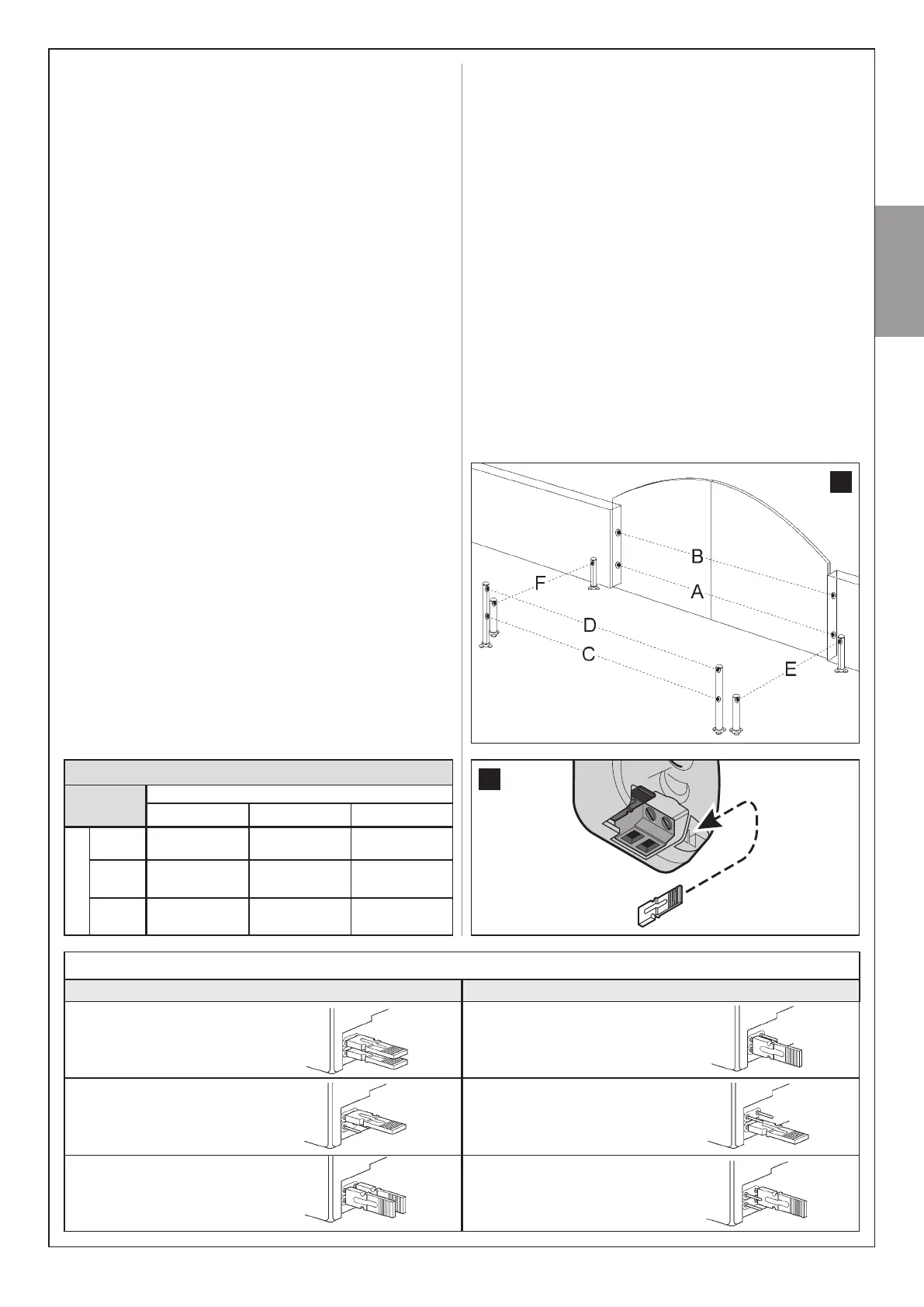
01. Install photocells TX and RX using one of the layouts shown in g. 37;
then connect the photocells to the control unit.
02. In Table 7 identify the position of the electric jumpers corresponding
to the layout used to install the photocells; then wire in the jumpers
in photocells TX and RX, with the same position as specied (note
– position jumpers not used in the relative compartment (g. 38), for
future use when necessary). Warning – As this conguration is used
by the control unit to recognise the specic pair of photocells and to
assign these with a specic function, take care to ensure that there
are no other pairs of photocells with jumpers wired in the same posi-
tion.
03. Perform the procedure described in paragraph A.10 for the control
unit to learn the identity of these new photocells.
A.10 - Learning the identity of new devices connect-
ed or removed
Each time new devices are connected to (or removed from) the terminals
“BUS” and “STOP” directly or indirectly, the control unit must learn the
identity of these devices. The following procedure enables the control unit
to recognise connected devices one at a time, and to assign them with a
specic unique address.
01. On the control unit, press and hold P2 until Led P2 starts ashing
quickly; then release the key.
02. Wait a few seconds for the control unit to learn all connected devices.
Learning is complete when the STOP Led remains lit and Led P2
turns off. Caution! – If Led P2 continues to ash this means that there
is an error; in this case read paragraph D - “Troubleshooting”.
03. Repeat the automation testing procedure as described in the para-
graph 9.1 “Testing”.
Caution! – In the future, if a new device is connected to the control unit
(for example, a new pair of photocells), or if a device is removed, this
learning procedure must be repeated.
37
A
Photocell h=50 cm;
with activation on closurea
B
Photocell h=100 cm;
with activation on closure
C
Photocell h=50 cm; with activation
on opening and closure
D
Photocell h=100 cm; with activation
on opening and closure
E
Photocell on right with activation
on opening
F
Photocell on left with activation
on opening
Table 7
B - ADVANCED SETTINGS
The control unit of the ALTO system has a series of modiable param-
eters to enable adaptation of the product to specic needs of the automa-
tion and relative users.
To modify a value or check a setting, use a transmitter memorised
in “Mode I” (if necessary, memorise on as described in paragraph C.2).
B.1 - Modifying the value of a parameter
Warning - During the procedure, the specied key must be pressed for
approx. 1 second, ith a pause of approx. 1 second before pressing
again. This ill give the control unit the time to recognise the command
sent via radio.
01. In Table 8 select the parameter to be modied (the meaning of the
parameters is provided in paragraph B.2) and note down the value to
be set, the transmitter key used to set this value and the number of
times the key is pressed to set the required value.
02. On the transmitter, press and hold keys T1 and T2 or T1 and T3
simultaneously (see Table 8) for at least 5 seconds; then release the
keys.
03. (within 3 seconds) Modify the selected parameter value by pressing
a transmitter key for a specic number of times; the relative key and
number of times to press are specied in Table 8. Example: to set
the Pause time at 40 seconds, press T1 three times.
Table 6
1
st
device
NA NC 8,2kΩ
2
nd
device
NA
In parallel
(note 2)
(note 1) in parallel
NC
(note 1)
In series
(note 3)
In series
8,2kΩ
in parallel In series
in parallel
(note 4)
38
 Loading...