CBOX1050
Installation and Programming Manual
2121
MX4682 Rev. D ©2021
7.1 POWER OPTIONS AND WIRING
There are four possible configurations available to power the 1050 control board:
• 12 VDC battery charged by solar panel
• 12 VDC battery charged by AC-DC charger applied to battery
• 12 VDC battery charged by 10-35 VDC from Main DC Power input
• 10-35 VDC (20A min.) from AC-to-DC power supply to Main DC Power input (no battery)
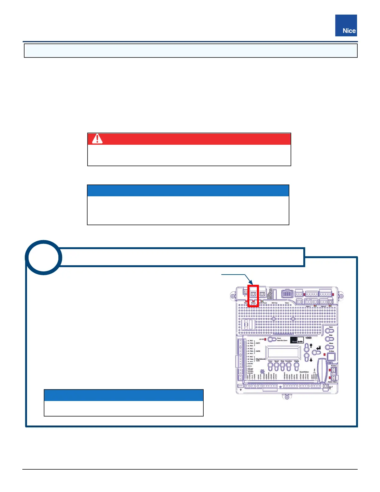
1. Remove BATTERY panel connector from control board
(IMAGE 8-1).
2. Retrieve black/red battery cable from kit, strip bare wires back
3/8”-7/16” (10-11mm), twist, and install into the Battery panel
connector screw terminals (RED = +, BLACK = -).
3. Attach lugs of the battery cable to the battery terminals; black
to negative (-) and red to positive (+) terminals.
4. Plug battery connector back in control board (IMAGE 8-1).
8
BATTERY POWER - INPUT CONNECTIONS
BATTERY POWER
INPUT CONNECTOR
IMAGE 8-1: BATTERY POWER
INPUT CONNECTOR
DANGER
Do not connect ac power directly to main dc power connector
on control board! The board accepts only 10-35 VDC!
IMPORTANT!
Power should not be applied to the control board until after the
photo eyes have been installed and wired to the control board.
Power is applied in INSTRUCTION 8.
NOTICE
LED below the terminal will glow red if mis-wired.
 Loading...