3
2
C P/B L
L
N
FUSE
N
1345 6
DOWN
COMMON
UP
STEP-BY-STEP
TT2N
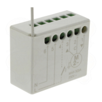
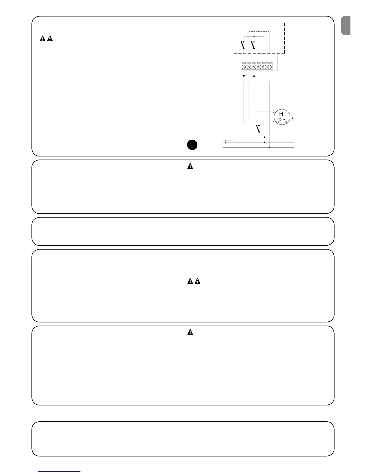
2.2.1) Motor connection
The single phase asynchronous motor connection to the mains must
be via terminals 1-2-3 (Down, Common, Up). Down corresponds to
the key t of the transmitters, Up to key s (direction of wind speed
sensor activation). After connecting, if the direction of motor rotation
is incorrect, exchange the connections of terminals 1 and 3.
Never connect more than one motor per control unit, if neces-
sary use the specific TTE expansion modules.
2.2.3) Step-by-step pushbutton
If required, a step-by-step pushbutton can be connected, which
when pressed activates a step with the sequence: Up- Stop-Down-
Stop. The pushbutton is connected between phase (L) and terminal
4 as shown in figure 3. If the pushbutton is pressed for more than
3 seconds, but less than 10, an up manoeuvre is always activated
(corresponding to key s of the transmitters). If the key is pressed
for more than 10 seconds, a descent manoeuvre is always activated
(corresponding to key t).
This function may be useful to synchronise several motors for the
same manoeuvre regardless of the current status.
The pushbutton carries mains voltage and must therefore be
adequately protected and insulated.
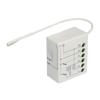
2.2.4) Climatic sensors
A maximum of 3 VOLO S RADIO climatic radio sensors can be man-
aged by the TT2N control unit. A VOLO S RADIO sensor is memo-
rised in the same way as a normal transmitter (tables A1 or A2).
The levels of activation can be programmed directly on the VOLO S
RADIO sensor. Activation of the wind sensor has priority over those
of the sun or rain and inhibits all controls for 1 minute (transmitters,
step-by-step pushbutton, activation of sun and/or rain sensors).
For further information see the instruction manual for VOLO S
RADIO.
Activation of the wind speed sensor (wind) causes movement
in the direction corresponding to key s of the transmitters.
2.2.2) Power supply
The electric power supply of the control unit must be connected by means of terminals 5 and 6 (Phase, Neutral). The TT2N control unit can
operate with either supply voltages of 120 or 230 V and frequency of 50 or 60 Hz.
2.2) Electrical connections
• Carefully follow all the connection instructions. If you have
any doubts do not make experiments but consult the rel-
evant technical specifications which are also available on
the web site: www.niceforyou.com. An incorrect connection
may be dangerous and cause damage to the system.
• The TT2N control unit does not feature any protection
against overload or short circuits on outlets. Adequate
overload protection should be envisaged on the power sup-
ply line, such as a fuse with the maximum values of 3.15 A.
3
To ensure that a transmitter can control the TT2N unit, the memorisation procedure must be performed as described in table A1. Memorisa-
tion and settings can be entered via the transmitters (paragraph 3.1) or directly via the programming pushbutton (paragraph 3.2).
3) Settings
EN
 Loading...