The ASCENT and DESCENT inputs do not control movement.
Make sure that the control unit is powered correctly: there must be
mains voltage between terminals 10-11. When the keys are open
between terminals 12-15 and 13-15, the voltage should be mea-
sured at approximately 24 Vdc. Check the integrity of the 5 A fuse.
The sensors are installed and there is light or wind, but
the LEDs do not switch on when you rotate the trimmers.
Check the climatic sensors have been connected correctly.
4) What to do if… a short troubleshooting guide!
5) Technical characteristics
Nice S.p.a., in order to improve its products, reserves the right to modify their technical characteristics at any time without prior notice. In
any case, the manufacturer guarantees their functionality and fitness for the intended purposes.
Note: all technical specifications refer to a temperature of 20°C.
Power supply 230 Vac 50/60 Hz
motor maximum power 600 W
Signal voltage (ascent, descent, sensors) approx circa 24 Vdc
Operating temperature -20 ÷ 55 °C
Dimensions / weight 128.5 x 111.5 x 43.5 mm / 340 g
Protection class “IP” 55 (container undamaged)
Wind sensor levels (anemometer) 5÷60 Km/h (with a 0.4 Hz anemometer for Km/h).
Sun sensor levels 5-60 K/lux (with “Volo S” anemometer)
Length of signal cables (ascent, descent, sensors) max. 3 m if near other cables, otherwise 100 m.
3) Programming
3.1) Dip-switch
The TT3 control unit has a 2 way dip-switch.
Dip-switch No. 1: permits the user to enable or disable the stop
command of the motor: OFF = stop enabled, ON = stop disabled;
the sequence when the stop is enabled will be: ascent-stop or
descent-stop; when the stop is disabled, it will be ascent or descent.
It will, therefore, be impossibile to stop the motor.
Dip-switch No. 2: enables the user to establish the direction for the
“rain” triggering. If the switch is OFF the “rain” triggering will activate
a descent manoeuvre, if ON it will activate an ascent manoeuvre
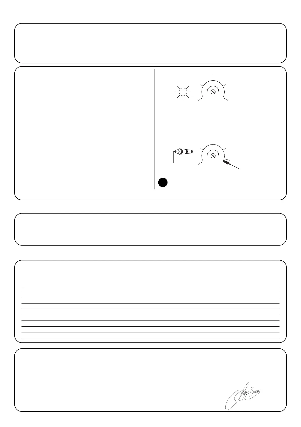
3.2) Adjusting the triggering thresholds
Rotate the trimmers according to the values shown in Fig. 5 in order to
adjust the “sun” and “wind” triggering thresholds.
• Wind: the “wind” sensor measures the speed of the wind in real time,
and communicates this information to the control unit. When the speed
exceeds the threshold set using the trimmer, the “wind” LED will switch
on and the control unit will control an ascent manoeuvre. After an
ascent command caused by the wind, the control unit will block any
other command for 1 minute (the “wind” LED will flash during this time)
and blocks the command caused by the sun for 10 minutes. If, during
testing, the user wishes to remove the block caused by the “wind”
command, s/he simply has to switch the power supply to the control
unit off or rotate the “wind” trimmer to maximum for a brief moment.
• Sun: the “sun” sensor measures the intensity of solar radiation in real
time, and communicates this information to the control unit. When the
intensity of the light exceeds the threshold set using the trimmer, the
“sun” LED will switch on and after 2 minutes the control unit will com-
mand a descent manoeuvre. When the intensity of the light drops to
under the threshold, the “sun” LED will flash for 15 minutes, after which
the control unit will command an ascent manoeuvre.
 Loading...