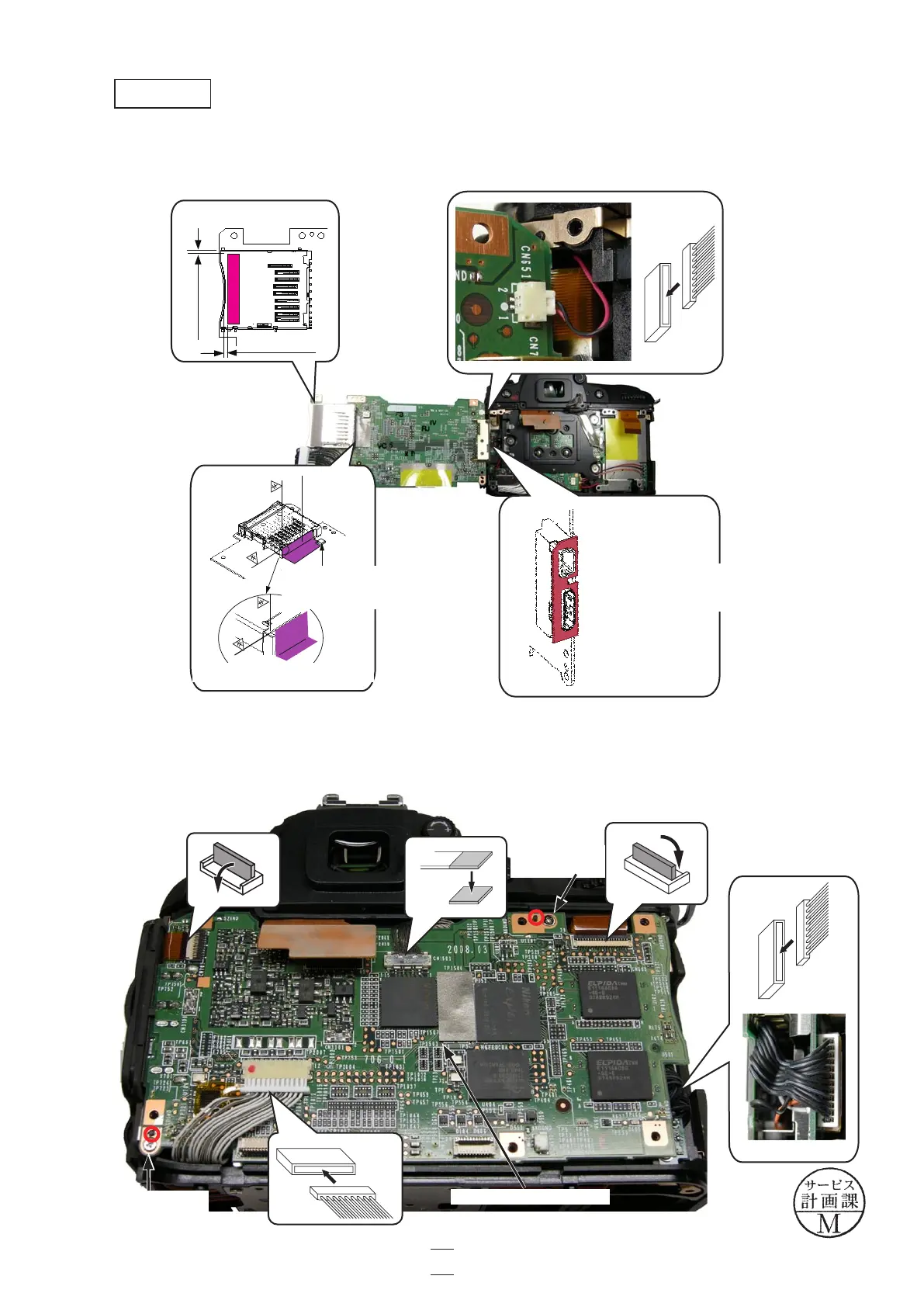
・Connect the connector of the microphone.Connect the connector of the microphone.
・Attach the gaskets (#480, #481 and #487).Attach the gaskets (#480, #481 and #487).
・Mount the DG PCB unit (#B1031) by fitting with bosses.Mount the DG PCB unit (#B1031) by fitting with bosses.
・Tighten the two screws (#683).screws (#683).
・Connect the three FPCs and the two harnesses.Connect the three FPCs and the two harnesses.
Screw
×1
(#683)
DG PCB unit (#B1031)
DG PCB unit
基準に合わせ谷折
しながら貼付ける
487
傾斜センサーにかか
っていないこと
基準部拡大図
0.5mm~1mm
0.5mm~1mm
481貼付け位置
(#480)
(#481)
(#487)
The gasket must not touch the
inclination sensor.
Closeup: reference position
Attach by fitting with
the connector section.
Screw
×1
(#683)
VBA23001-R.3762.A
- A77 ・ D90 -
A74
Changed page △×1
△(Revision)
October. 2. 2008
 Loading...