Procedure
①
While mount the top cover not by tightening the screws but by only connecting the FPC, make temporary assembly of
the grip cover and I/F cover into the bottom cover (with tripod attached) with four screws.
②
Mount "AF50/1.4D" on the camera, and x them on the tripod horizontally.
③
Connect the camera and PC via USB cable (UC-E4).
④
Connect the AC adapter EH-5.
*
Be careful NOT to cause a short-circuit at uncovered portions.
⑤
Attach the AE-CCD positioning tool (J
63108
) in the color viewer (J63070), and turn power ON.
⑥
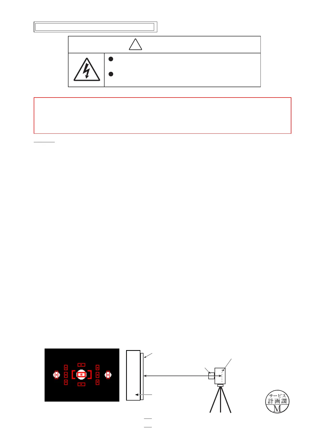
Keep the 0.7-m distance between the front face of the AE-CCD positioning tool and the reference surface of the camera.
Set the camera AF to manual, and rotate the focus ring to set to "0.7 m".
⑦
Start up the inspection and adjustment software for D90 (J65126), and select "Inspection and Adjustment for AE CCD
POSITION" then "Set Camera for AE CCD POSITION" to display the focus areas.
Looking through the viewnder, move the camera so that the focus areas are positioned on the AE-CCD positioning tool
as below Fig.
*
Set the camera and AE-CCD positioning tool horizontally.
⑧
Select "Inspection and Adjustment for AE CCD POSITION".
*
Cover the camera with a black cloth, etc, when measured.
⑨
Place the metering FPC unit and turn the three screws (#514) until they are lightly attached, and then give them 1.5-turns
counterclockwise. By following the instructions on PC, adjust the AE-CCD position by using the screws [a (#514) and
b (#514)].
⑩
Fix the three screws with the screwlock
.
⑪
After completing the adjustment, secure the top cover with the screw, and inspect accuracy. If the result does not meet
the standard, make the readjustment.
Approx 0.7 m
AE-CCD positioning
tool (J63108
)
AF 50/1.4D
Attaching surface of the imaging-PCB
Color viewer (J63070)
WARNING
There are high voltege parts inside. Be careful of this electric shock,
when you remove the cover.
You must discharge the main condenser according to the instruction
of this repair manual after you remove the cover.
!
*
Under the environment where the AE-CCD positioning is adjusted, use the reference body and conrm results.
・
In case the measured value is out of standard, check whether there is no deviation of the focus area positioning.
・
In case the measured value is out of standard, change the environment of measurements. (e.g. setting place/direction,
room brightness, etc)
Inspection and adjustment of AE CCD positioning
Fig.
VBA23001-R.3762.A
- A69 ・ D90 -
A75
Changed page △×1
△(Revision)
October. 2. 2008
 Loading...