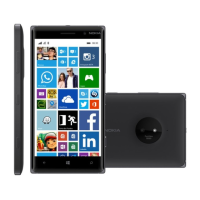
AHJ connector
The AHJ connector handles both audio and video signals output. It has audio left and right signals separately
(pins 4 and 7) and the microphone signal wired to pin 2.
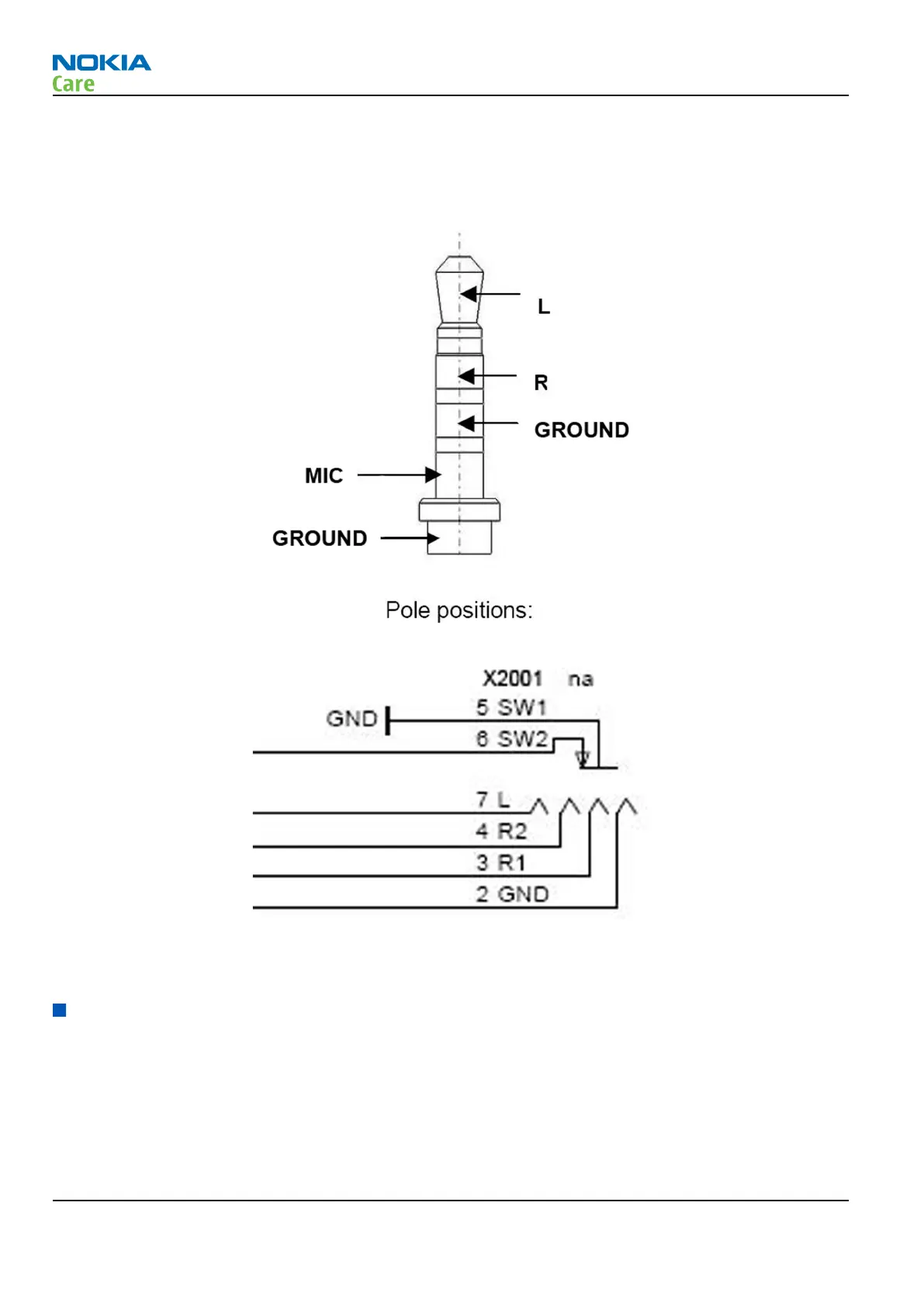
Figure 54 AHJ connector pole positions
Figure 55 AHJ connector diagram
The plug detection signal handles the AHJ connector plug detection with HS_DET signal from WCD9310.
Cellular RF technical description
The RM-825 transceiver unit supports GSM 850/900/1800/1900, EGPRS (EDGE), WCDMA Band I (2100), II (1900),
V (850) and VIII (900), LTE B1/B3/B7/B8/B20, and HSPA. The transceiver is compatible with 3GPP Release 6
specification, and supports Bluetooth 2.1+EDR standard and WLAN a/b/g/n (2.4 GHz and 5.0 GHz). The
transceiver consists of a system/RF module which is referred to as the engine, a Bluetooth/WLAN/FM module,
and a GPS module for use while the engine is operating in either GSM or WCDMA mode.
The transceiver consists in one PWB. Located on the top side of the PWB it consists of RF, BT, WLAN and GPS
engines.
RM-824; RM-825; RM-826
System Module
Page 6 – 26 NOKIA INTERNAL USE ONLY Issue 2
Copyright © 2012 Nokia. All rights reserved.
 Loading...