AFP-200 Instruction PN 15511:F2 10/11/99 13
1.7 Optional Devices
1.7.1 Digital Communicator
The 911AC Digital Alarm Communicator/Transmitter mounts in a separate enclosure (Figure B-1) and connects
to the control panel. The 911AC transmits three zones of information (System Alarm, System Trouble, Supervi-
sory) to the central station or remote station receiver. Fully UL-Listed for fire operation (NFPA 72-1993), the
911AC requires two standard dial-up telephone lines to operate. For details, refer to the 911AC Manual,
Document 74-06200-005.
1.7.2 UDACT
The Universal Digital Alarm Communicator/Transmitter (UDACT) can be used with the control panel. The
UDACT transmits system status to UL-listed Central Station Receivers via the public switched telephone
network. The UDACT mounts externally in a separate enclosure. EIA-485 annunciator communications bus
and 24 VDC (nominal) connections are required. The UDACT is capable of reporting the status of 89 zones
when used with the AFP-200. The AFP-200 requires software PN 73609 or higher when using a UDACT.
Refer to Appendix B of this manual and the UDACT Manual for additional information.
1.7.3 Option Slot
The circuit board includes an option module slot located on the right side of the board. When an option module
is installed, jumper JP5 located to the right of the membrane switch panel must be cut. The option slot supports
one of the modules described below.
4XTM Transmitter module
This module provides municipal box and remote station transmitters meeting NFPA 72-1993 Auxiliary and
Remote Station requirements. Disable switch and indicator are included.
RTM-8 Relay Module
The relay/transmitter Module (RTM-8) module provides eight Form-C relays (5A contacts). These relays track
Software Zones 1 through 8. The RTM-8 also provides Municipal Box and Remote Station transmitters.
Equipped with an RTM-8, the AFP-200 meets NFPA 72-1993 (Auxiliary) and NFPA 72-1993 (Remote Station)
requirements. In remote station applications, the RTM-8 transmits alarm only and does not
transmit trouble or supervisory status. Disable switches and indicators are included.
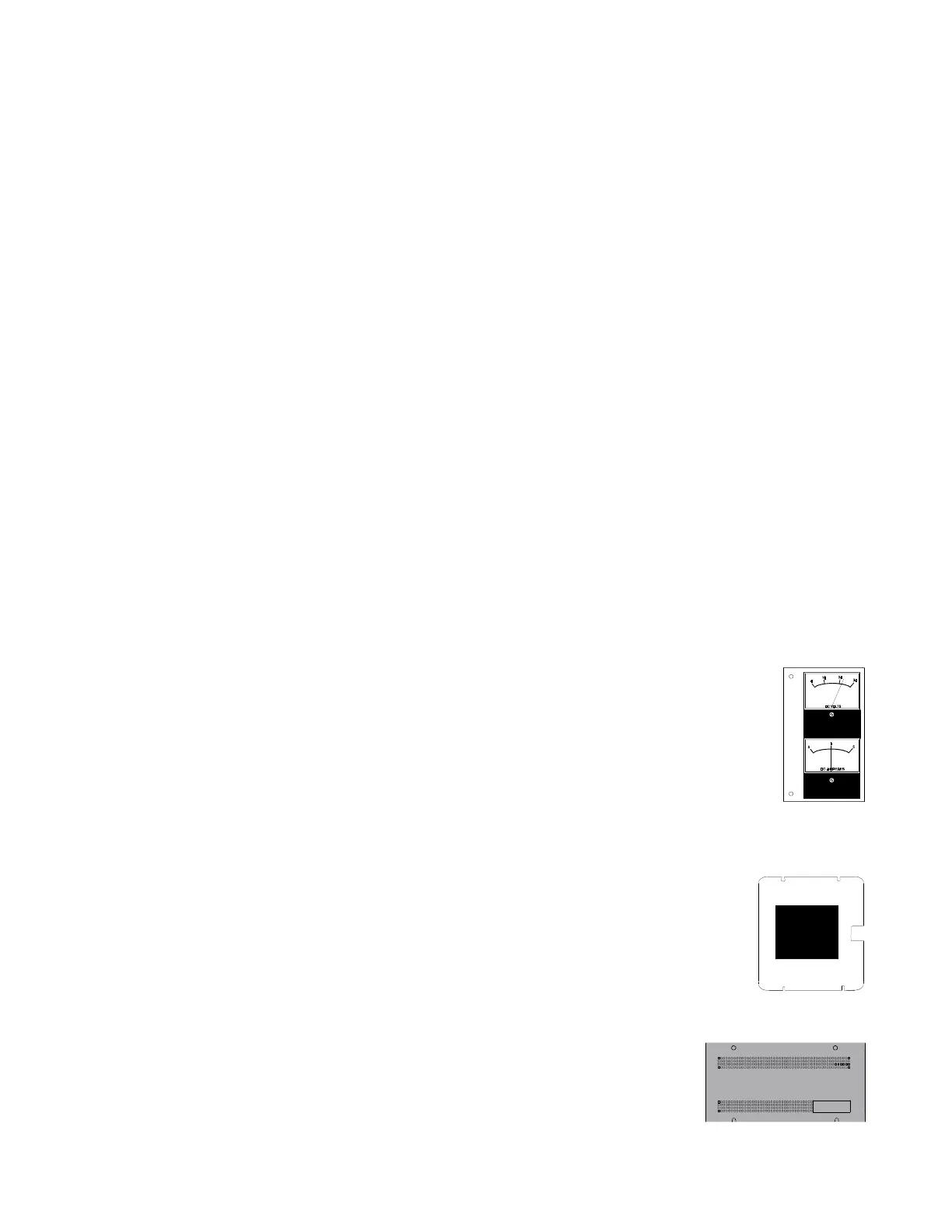
Meter Module
The 4XMM Meter Module provides a voltmeter to measure voltage across the batteries and an
ammeter to measure charging current to the batteries. A single assembly containing both meters
mounts in the lower left-hand corner of the AFP-200 cabinet.
Trim Ring
The TR-4XG gray trim ring is available for semi-flush mounting of the control panel cabinet.
Battery Box
The BB-17 battery box may be used to mount two 17 AH batteries. The box mounts directly
below the control panel cabinet.
Dress Panel
A dead front dress panel (DP-AFP200) is available as an option (required for Canadian
installations).
Expansion Power Supply
Power supply model AVPS-24/AVPS-24E provides an additional 3 A of notifica-
tion appliance power. Refer to the Device Compatibility Document for compatible
notification appliances.
Marine Cabinet
Cabinet CAB-AM is required for applications requiring United States Coast Guard
or Lloyd's Register approvals.

 Loading...


