CLASS “A” WIRING CIRCUIT AND LINE ISOLATORS
Functions in accordance with NFPA STYLE 7 Signaling Line Circuit
»
Note: the number of addressable devices between ISO-X modules must not exceed 25 devices.
OPERATION
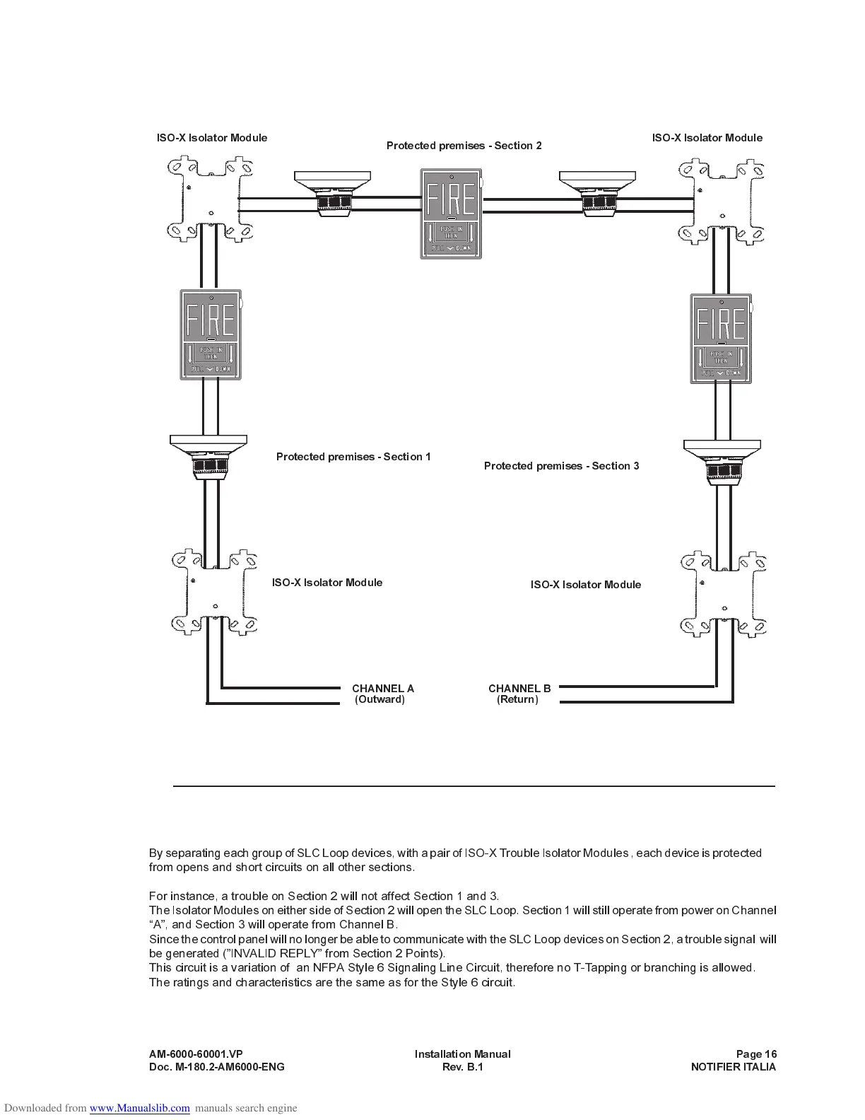
By separating each group of SLC Loop devices, with a pair of ISO-X Trouble Isolator Modules , each device is protected
from opens and short circuits on all other sections.
For instance, a trouble on Section 2 will not affect Section 1 and 3.
The Isolator Modules on either side of Section 2 will open the SLC Loop. Section 1 will still operate from power on Channel
A, and Section 3 will operate from Channel B.
Since the control panel will no longer be able to communicate with the SLC Loop devices on Section 2, a trouble signal will
be generated (INVALID REPLY from Section 2 Points).
This circuit is a variation of an NFPA Style 6 Signaling Line Circuit, therefore no T-Tapping or branching is allowed.
The ratings and characteristics are the same as for the Style 6 circuit.
AM-6000-60001.VP Installation Manual Page 16
Doc. M-180.2-AM6000-ENG Rev. B.1 NOTIFIER ITALIA
ISO-X Isolator Module
Protected premises - Section 2
ISO-X Isolator Module
ISO-X Isolator Module
ISO-X Isolator Module
Protected premises - Section 1
Protected premises - Section 3
CHANNEL A CHANNEL B
(Outward) (Return)
 Loading...


