•
•
Air Flow
The systems are offered with two air flow patterns:
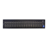
Power (rear) side inlet to connector side outlet - marked with blue power supplies/fans FRUs’
handles or blue dots that are placed on the power inlet side.
Air Flow Direction Marking - Power Side Inlet to Connector Side Outlet
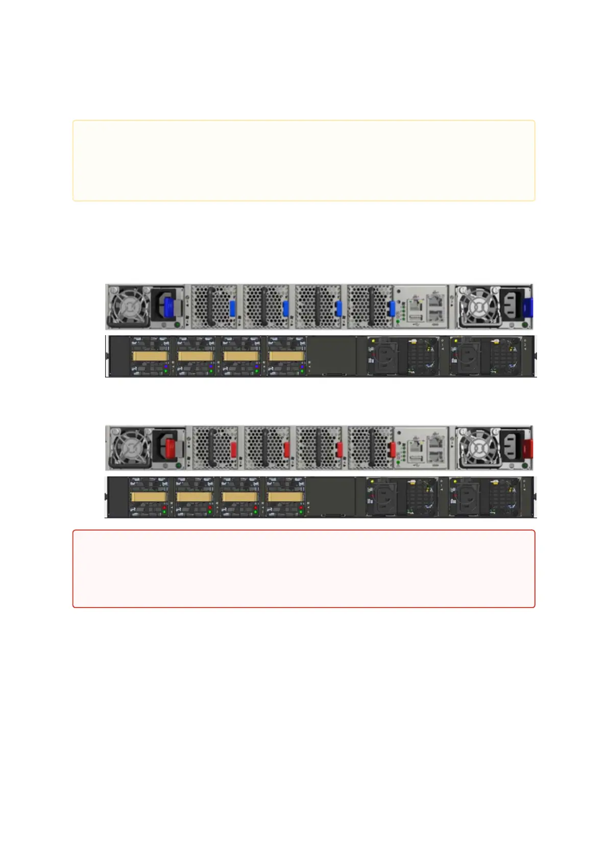
Connector (front) side inlet to power side outlet - marked with red power supplies/fans FRUs’
handles or red dots that are placed on the power inlet side.
Air Flow Direction Marking - Connector Side Inlet to Power Side Outlet
The table below provides an air flow color legend and respective OPN designation.
•
•
The following information does not apply to SN2100/SN2010. In the SN2100/SN2010
systems, the fan units are non-replaceable.
The drawings are provided for illustration purposes only. The panel and modules
design may vary depending on the system.
All servers and systems in the same rack should be planned with the same airflow direction.
All FRU components need to have the same air flow direction. A mismatch in the air flow
will affect the heat dissipation.
 Loading...