Oki Data CONFIDENTIAL
44871001TH Rev.6
6-16
6. MAINTENANCE MENUS
6.4.2 Ordinary self-diagnostic mode (level 1)
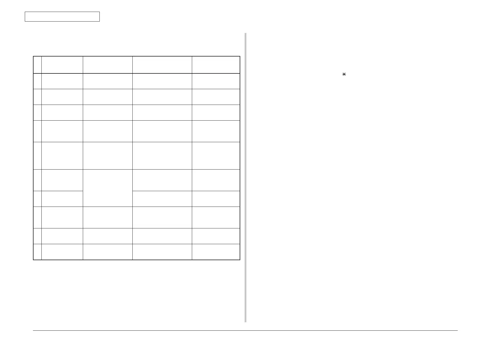
Menu items of the ordinary self-diagnostic mode are shown below.
Item
Self-diagnostic
menu
Adjustment contents
Maintenance
utilities
1
Switch scan test SWITCH SCAN Entry sensor check and
switch check
Refer to 5.3.1 No.21
2
Motor clutch test MOTOR&CLTCH
TEST
Motor and clutch
operation test
Refer to 5.3.1 No.22
3
Test print
execution
TEST PRINT PU built-in test pattern
print
It is not possible to
operate it.
4
Consumable item
counter display
CONSUMABLE
STATUS
Consumable items
consumption status
display
Refer to 5.3.1 No.23
5
Consumable item
accumulative
counter display
PRINTER STATUS Consumable items
accumulative
consumption status
display
Refer to 5.3.1 No.23
6
Factory/Shipping
mode selection
FACTORY MODE
SET
Switching between the
Factory mode and the
Shipping mode
Refer to 5.3.1 No.3,
No.24
7
FUSE status
check
Respective FUSEs status
display
Refer to 5.3.1 No.3,
No.24
8
Engine parameter
setting
SENSOR SETTING Valid/Invalid setups of
error detection by various
sensors
Refer to 5.3.1 No.25
9
LED Head serial
number display
LED HEAD DATA LED Head serial number
display
It is not possible to
operate it.
10
NVRAM
parameter setting
NVRAM
PARAMETER
Do not use this item It is not possible to
operate it.
6.4.2.1 Entering self-diagnostic mode (level 1)
1. Make sure that the LCD is in standby state (no Error window is shown) and
press the [Setting] to move to the setting widow and then press the following
button in the indicated sequence.
[#]
→
[0]
→
[1]
→
[0]
→
[3]
→
[
]
2. Type in the password to enter Service Maintenance Menu. It is [000000] by
default. (Enter 0 six times)
3. Select [Printer Maintenance]
→
[Engine Diag Mode] in the Service Maintenance
Menu and press the [6].
6.4.2.2 Exiting self-diagnostic mode
1. When the [4] is pressed from Diag Mode (Window displaying/Factory state), the
setting window will return.
 Loading...