Oki Data CONFIDENTIAL
44871001TH Rev.6
8-59
8. TROUBLESHOOTING PROCEDURES
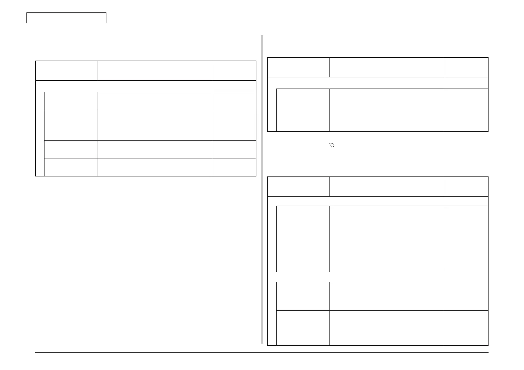
8.5.5. (8) Paper size error (Error code 400)
(8-1) Jam occurs when paper end is located near the entrance sensor.
Check item Check operation
Actions for NG
results
(8-1-1) Check paper size and respective sensor.
Paper size Is the paper which is specified size used? Use a specified-
size paper.
Entrance sensor Does the entrance sensor lever work normally?
(It moves freely by touching.)
Replace the
entrance sensor
lever, or clean the
entrance sensor.
Write sensor Does the write sensor lever work appropriately?
(It moves freely by touching.)
Replace the write
sensor lever.
Main board Clean the write sensor. Replace the main
board.
8.5.5. (9) Fuser unit error (Error 170 to 177)
(9-1) Error occurs immediately after the power is turned on.
Check item Check operation
Actions for NG
results
(9-1-1) Thermistor is defective Note)
Thermistor Check the thermistors if they are shorted or
opened internally.
Check the resistance value at the connector pins
in the bottom of the fuser unit.
(Refer to section 9.1 Resistance check (fuser
unit).)
Replace the fuser
unit.
Note! Service calls 171 error and 171 error can occur when the printer temperature
is below 0
. Turn on the power again after the printer temperature has
increased.
(9-2) Error occurs approx. 1 minute after the power is turned on.
Check item Check operation
Actions for NG
results
(9-2-1) Temperature increase of fuser unit
Thermostat,
halogen lamp
Heater of the fuser unit is controlled of its
temperature. Check if the fuser unit gets hot or
not by touching it with hands.
If the fuser unit temperature does not increase
and remains cold, check that the resistance
between pin-1 and pin-2, and that in between
pin-3 and pin-4 of the two connectors is in the
range of several ohms to several ten ohms
respectively. (Refer to section 9.1 Resistance
value (fuser unit).)
Replace the fuser
unit.
(9-2-2) AC power input to the halogen lamp
AC power voltage
from the low voltage
power supply
Check if the AC voltage for heater is normally
supplied or not.
Power supply J2 connector, between pin-1 and
pin-2.
Replace the low
voltage power
supply.
Heater ON signal
that is output from
CU/PU to the low
voltage power
supply
Check that the heater ON signal goes active at
the warming up timing, or not.
"L" active while ON.
CU/PU board POWER connector 15 pin.
Replace the
CU/PU board.
 Loading...