Oki Data CONFIDENTIAL
44871001TH Rev.6
8-62
8. TROUBLESHOOTING PROCEDURES
8.5.5. (14) Toner cartridge cannot be recognized. (Error code 540, 541, 542, 543)
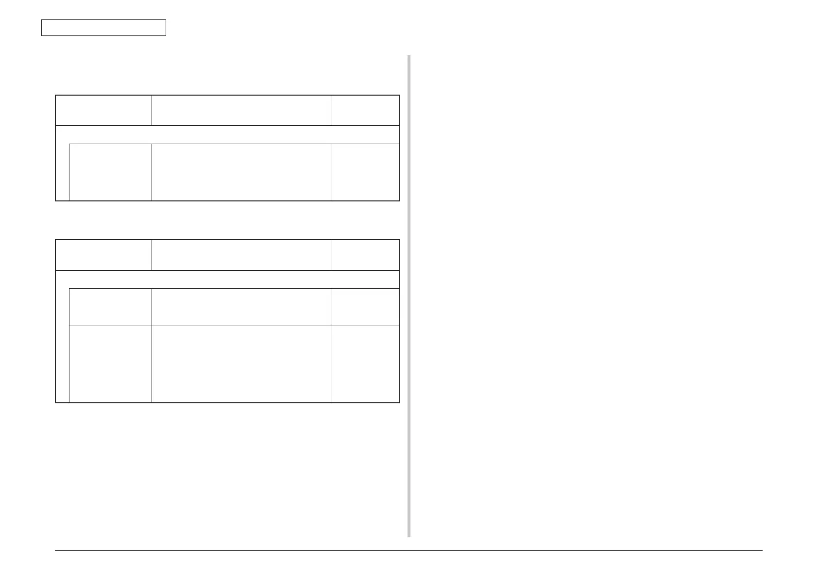
(14-1) Error caused by the consumable items.
Check item Check operation
Actions for NG
results
(14-1-1) Consumable items installation condition
ID unit and toner
cartridge
Check that the ID unit is installed in the normal
position. Check that the lock lever of the toner
cartridge is locked.
Correct the
installation
to the normal
installation
condition.
(14-2) Error caused by the toner sensor
Check item Check operation
Actions for NG
results
(14-2-1) Toner sensor condition
Toner sensor Is the receptor of the toner sensor stained? Wipe off the stain
from the toner
sensor.
Toner sensor Confirm that the toner sensor works normally by
using the SWITCH SCAN function of the self-
diagnostic mode.
Place a white paper in front of the toner sensor,
and check if the SCAN state changes or not.
Replace the toner
sensor board,
CU/PU board, or
FFC that is located
between the toner
sensor board and
the CU/PU board.
Note! Toner sensor operation check method using the SWITCH SCAN function of
the self-diagnostic mode.
(1) How to check operation of the toner sensor at the printer side.
1. Status change of the toner sensor can be checked from the Operator Panel
using the self-diagnostic mode. First, switch the display to the Operator Panel
display. For the method of switching the display to the Operator Panel display,
refer to section 5.4.3 Switch Scan Test
2. Remove the ID unit and the toner cartridge (TC) from a printer. There is a
window inside a printer opposing the ID side when viewed from the front of
a printer. The toner sensor is located inside the window.
3. Place a white paper 3 mm away from the sensor window. The white paper
should be placed in the manner of opposing the toner sensor.
4. When light is reflected by a white paper so that incident light falls on the
toner sensor, the Operator Panel display shows "L". When the paper is
moved so that any light is not reflected by the paper so that the incident light
does not reach the toner sensor, "H" is displayed on the Operator Panel.
5. If the Operator Panel display toggles between "H" <-> "L" as a paper is
flipped in front of the toner sensor, it indicates that the toner sensor and the
related system of the printer are working normally.
Action to be taken at NG
• Cleansurfaceofthetonersensortoremovethestainsduetoresidualtoner
and paper dust.
• ChecktheconnectionstatebetweentheCU/PUboardandthetonersensor
board (97T) that are connected with the FFC cable.
• Checkitonceagain,andifnochangehasfoundinthestate,replacetheCU/
PU board or the toner sensor board (97T).
(2) How to check operation of the toner sensor at the toner cartridge (TC) side
1. To the position where the toner sensor is confirmed to be operating normally
in the printer itself by the above paragraph (1), install the TC and the ID unit
to check operations by observing display on the Operator Panel.
2. If the ID unit works normally, the display on the Operator Panel will toggle
between "H" <-> "L" in synchronism with movement of the silver reflector
plate that is located on the side of the ID.
Action to be taken at NG
• CheckoperationconditionoftherespectiveIDmotorsbyusingtheMotor&
Clutch Test of the self-diagnostic mode.
• CleansurfaceofthesilverreectorplateonthesideofIDtoremovestains.
(Stain due to toner or paper dust)
• ReplacetheTCofdifferentcolorandtheIDunitasapair.
If a satisfactory operation is attained by using the a pair of TC of different
color and the ID unit, replace the TC or replace the ID unit.
 Loading...