CH10/CH20 C. DISASSEMBLY AND ASSEMBLY PROCEDURES
C-13
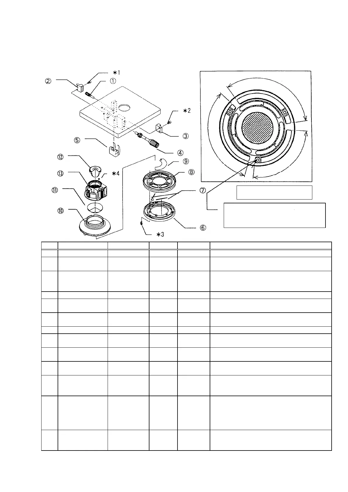
5. Condenser
118
°
118°
92.5°
Apply grease on the dovetail.
Apply grease on the dovetail.
±
13
and tighten the screws (*2)
so that the dovetail ƒ is attached without play.
Apply grease on the shaft sliding surface.
Apply grease on the spring sliding surface.
Apply a small amount of grease on the upper
frame boss sliding surface.
±
10
±
11
Assemble the lens with the convex side
Clean the lens using alcohol.
±
12
Assemble the lens with the convex side
Clean the lens using alcohol.
Apply adhesive between the lens frame and
±
13
Apply adhesive on the screw (AHU3X4SA)
after setting the stage height (-0.1 - 0.15 mm
from stage surface to condenser’s top end).
Figure-A (Showing the assembly of
lower frame and rotary ring)
Attach the lower frame (AD1994) at the position in
which the left end of minimum groove (width;
92.5°) in the rotary ring comes in contact with the
boss on the lower frame.
 Loading...