6
Communications Settings
6. Communications Settings
This section describes the contents of parameter and device variable settings that are all
defined in this document.
6.1. EtherCAT Connection Parameter
The parameter required for connecting Controller and Slave Terminal via EtherCAT is shown
below.
<Slave Terminal Setting>
Node address 1
Set the address using the hardware switches on Slave
Terminal.
6.2. IO-Link Connection Parameter
The parameter required for connecting IO-Link Master Unit and Photoelectric Sensor via
IO-Link is shown below.
In this document, Photoelectric Sensor is connected to Port 1 on IO-Link Master Unit.
<IO-Link Master Unit Setting>
Port1 IO-Link Device Configuration Data / Master Control
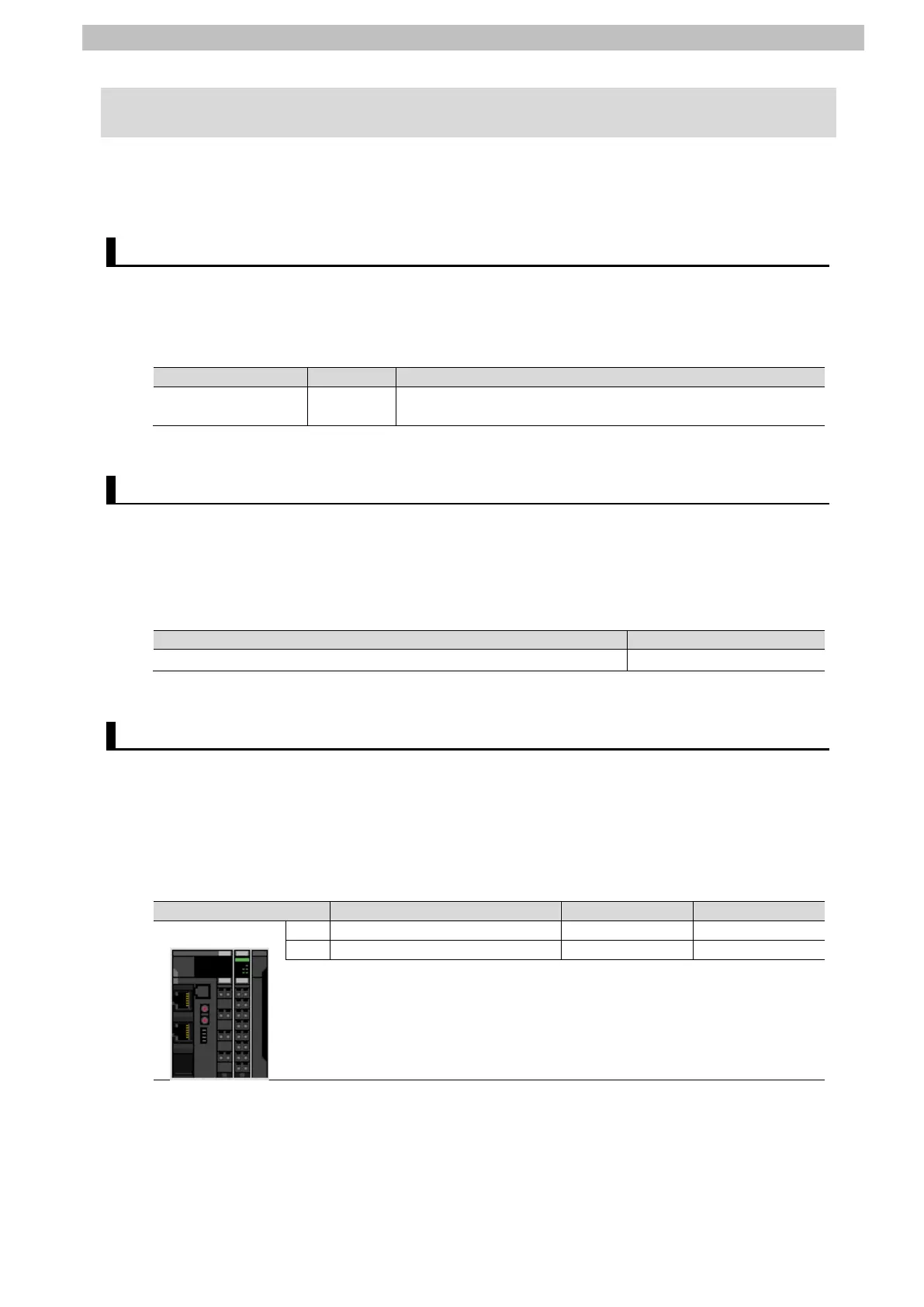
6.3. Slave Terminal Configuration and Device Names
The Slave Terminal configuration and device names are shown below.
The default values are used for the device names. For slave units, the default device names
are "E" followed by a serial number that starts from 001.
For NX Units, the default device names are N followed by a serial number that starts from 1.
<Slave Terminal configuration and device names>
 Loading...