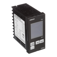
14 Digital Temperature Controllers E5CZ
Analog Input
Applicable standards by input type are as follows:
K: GB/T 2814-98
J,L: GB/T 4994-98
T,U: GB/T 2903-98
E: GB/T 4993-98
N: GB/T 17615-98
R: GB/T 1598-98
S: GB/T 3772-98
B: GB/T 2902-99
JPt100, Pt100: GB/T 5977-99
■ Characteristics
Note 1. The indication accuracy of K thermocouples in the −200 to 1300°C range, T and N thermocouples at a temperature of −100°C max. and
U and L thermocouples at any temperature is
±2°C ±1 digit maximum. The indication accuracy of the B thermocouples at a temperature
of 400
°C max. is not specified.
The indication accuracy of the R and S thermocouples at a temperature of 200
°C max. is ±3°C ±1 digit maximum.
2. Conditions: Ambient temperature:
−10°C to 23°C to 55°C, Voltage range: −15% to +10% of rated voltage.
3. When using the E53-CN03N or E53-CNBN Option Unit with the E5CZ-C2M or E5CZ-C2M to satisfy the Class A limit for the radiated in-
terference field strength test, always connect a ZCAT2235-1030 Clamp Filter (manufactured by TDK) to the power line of the Temperature
Controller.
Input type 0 to 50 mV
Setting range Usable in the following ranges by scaling:
−1999 to 9999 or −199.9 to 999.9
Setting number 21
Indication accuracy Thermocouple:
(
±0.5% of indicated value or ±1°C, whichever is greater) ±1 digit max. (See note 1.)
Platinum resistance thermometer:
(
±0.5% of indicated value or ±1°C, whichever is greater) ±1 digit max.
Analog input:
±0.5% FS±1 digit max.
CT input:
±5% FS±1 digit max.
Influence of temperature
(See note 2.)
R, S, and B thermocouple inputs:
(
±1% of PV or ±10°C, whichever is greater) ±1 digit max.
Other thermocouple inputs:
(
±1% of PV or ±4°C, whichever is greater) ±1 digit max.
*
±10°C for −100°C or less for K sensors
Platinum resistance thermometer inputs:
(
±1% of PV or ±2°C, whichever is greater) ±1 digit max.
Analog inputs:
(
±1% of FS) ±1 digit max.
Influence of voltage
(See note 2.)
Hysteresis 0.1 to 999.9 EU (in units of 0.1 EU)
Proportional band (P) 0.1 to 999.9 EU (in units of 0.1 EU)
Integral time (I) 0 to 3999 s (in units of 1 s)
Derivative time (D) 0 to 3999 s (in units of 1 s)
Control period 1 to 99 s (in units of 1 s)
Manual reset value 0.0% to 100.0% (in units of 0.1%)
Alarm setting range
−1999 to 9999 (decimal point position depends on input type)
Sampling period 500 ms
Insulation resistance 20 M
Ω min. (at 500 VDC)
Dielectric strength 2,000 VAC, 50 or 60 Hz for 1min (between current-carrying terminals of different polarity)
Vibration resistance
10 to 55 Hz, 20 m/s
2
for 10 min in X, Y and Z directions
Shock resistance
100 m/s
2
, 3 times each in 3 axes, 6 directions
Weight Approx. 150 g
Memory protection EEPROM (non-volatile memory) (number of write operations: 100,000)
EMC Enclosure Emission: EN 55011 (GB/T 6113.1,2) Group 1 Class A
AC Mains Emission: EN 55011 (GB/T 6113.1,2) Group 1 Class A
ESD Immunity: IEC 61000-4-2 (GB/T 17626.2) 4 kV contact discharge (level 2)
8 kV air discharge (level 3)
RF-interference Immunity: IEC 61000-4-3 (GB/T 17626.3): 10 V/m, 80 MHz to 1 GHz (level 3)
Conducted Disturbance Immunity: IEC 61000-4-6 (GB/T 17626.6): 3 V (0.15 to 80 MHz) (level 3)
Burst Immunity: IEC 61000-4-5 (GB/T 17626.5): 2 kV powerline (level 3)
2 kV I/O signalline (level 4)
Applicable standards UL 61010C-1, CSA C22.2 No.1010.1
Conforms to EN 61326, EN 61010-1 (IEC 61010-1).

 Loading...