16 Digital Temperature Controllers E5CZ
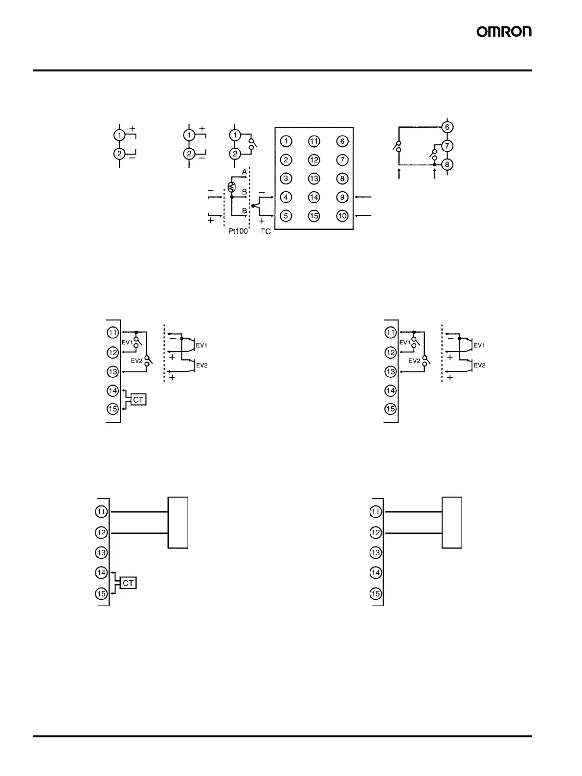
Wiring Terminals
• The voltage output (control output) is not electrically insulated from the internal circuits. When using a grounded thermocouple, do not connect
the control output terminals to the ground. If the control output terminals are connected to the ground, errors will occur in the measured temper-
ature values as a result of leakage current.
12 VDC
21 mA
Control output 1
Analog input Input power supply
Alarm output
Two input power supplies are available: 100 to 240 VAC or 24 VDC.
Voltage output Relay output
Current output
ALM2/Control
output 2
ALM1/Heater
burnout
4 to 20 mA DC
Contact inputs
Non-contact inputs
Heater burnout detection input
E53-CNBN
Event Inputs
Contact inputs
Non-contact inputs
Do not use.
Do not use.
E53-CNHBN
Event Inputs/Heater Burnout Detection
Do not use.
E53-CN03N
Communications
Do not use.
Do not use.
Do not use.
E53-CNH03N
Communications/Heater Burnout Detection
Host computer
Host computer
Option Units
Heater burnout detection input
B (+)
A (−)
RS-485
B (+)
A (−)
RS-485
Communications
Interface: RS-485
Synchronization: Start-stop
(asynchronous)
Communications: Half duplex
Baud rate: 1.2/2.4/4.8/9.6/
19.2 kbps
Event Inputs
Contact Inputs
ON: 1 k
Ω max., OFF: 100 kΩ min.
Non-Contact Inputs
ON: residual voltage of 1.5 V max.
OFF: leakage current of 0.1 mA max.
Heater Burnout Alarm
Maximum heater current: 50 A AC
Input current indication accuracy:
±5% FS ±1 digit max.
Heater burnout alarm setting range:
0.1 to 49.9 A, in 0.1 A increments

 Loading...