2.2 Wiring Terminals
2-5
2.2 Wiring Terminals
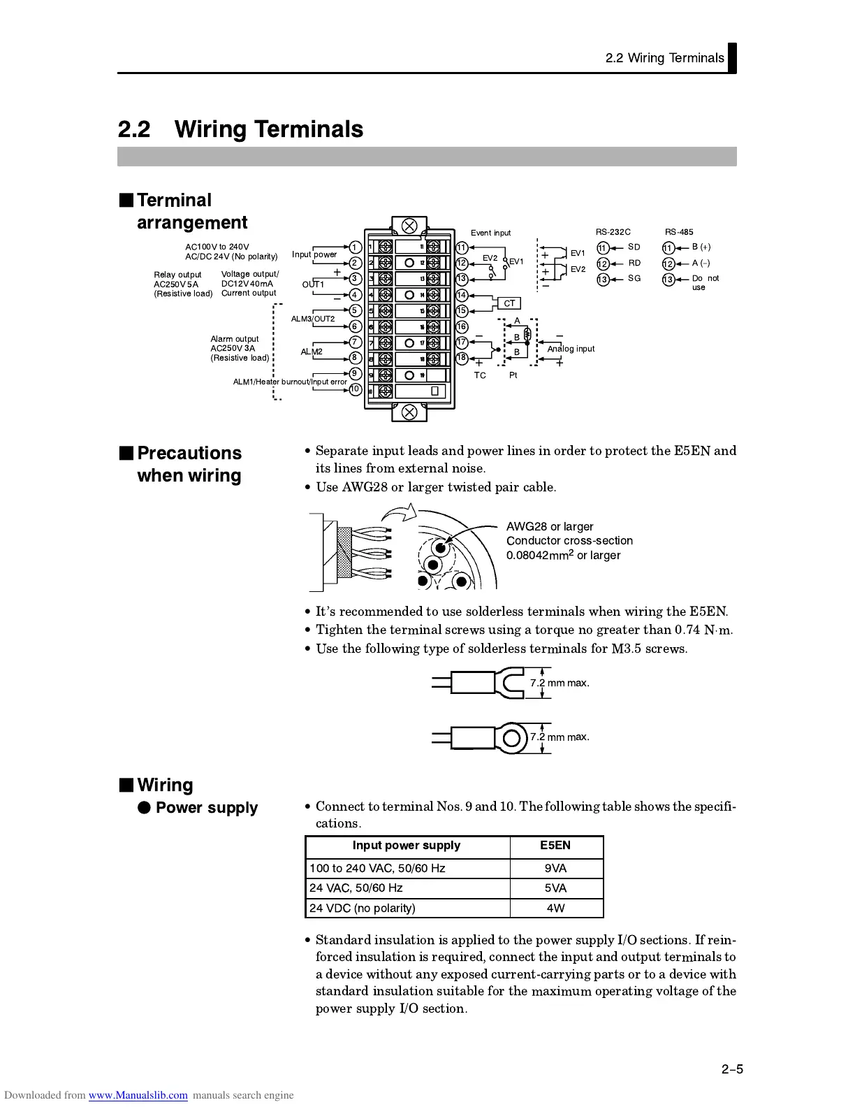
ALM1/Heater burnout/Input error
1
2
3
4
5
OUT1
6
7
8
9
10
ALM3/OUT2
Input power
AC100V to 240V
AC/DC 24V (No polarity)
ALM2
Voltage output/
DC12V 40mA
Current output
Relay output
AC250V 5A
(Resistive load)
Alarm output
AC250V 3A
(Resistive load)
Analog input
EV1
CT
A
B
B
11
12
13
14
15
16
17
18
Event input
EV2
SD
11
12
13
11
12
13
RD
SG
B (+)
A (-)
Do not
use
RSĆ232C RSĆ485
TC Pt
EV1
EV2
•
(*, #&(-, $+ & ('/* $#&+ #& '** ,' (*',, ," &
#,+ $#&+ *'% 0,*&$ &'#+
•
+ '* $*!* ,/#+, (#* $
AWG28 or larger
Conductor crossĆsection
0.08042mm
2
or larger
•
,+ *'%%& ,' -+ +'$*$++ ,*%#&$+ /"& /#*#&! ,"
•
#!",& ," ,*%#&$ +*/+ -+#&! ,'*)- &' !*,* ,"&
%
•
+ ," '$$'/#&! ,1( ' +'$*$++ ,*%#&$+ '* +*/+
7.2 mm max.
7.2 mm max.
•
'&&, ,' ,*%#&$ '+ & " '$$'/#&! ,$ +"'/+ ," +(# #3
,#'&+
Input power supply E5EN
100 to 240 VAC, 50/60 Hz 9VA
24 VAC, 50/60 Hz 5VA
24 VDC (no polarity) 4W
•
,&* #&+-$,#'& #+ (($# ,' ," ('/* +-(($1 +,#'&+ *#&3
'* #&+-$,#'& #+ *)-#* '&&, ," #&(-, & '-,(-, ,*%#&$+ ,'
.# /#,"'-, &1 0('+ -**&,3**1#&! (*,+ '* ,' .# /#,"
+,&* #&+-$,#'& +-#,$ '* ," %0#%-% '(*,#&! .'$,! ' ,"
('/* +-(($1 +,#'&
J
Terminal
arrangement
J
Precautions
when wiring
J
Wiring
F
Power supply

 Loading...


