54
Screw-less Clamp Terminals Section 4-2
Output Specifications
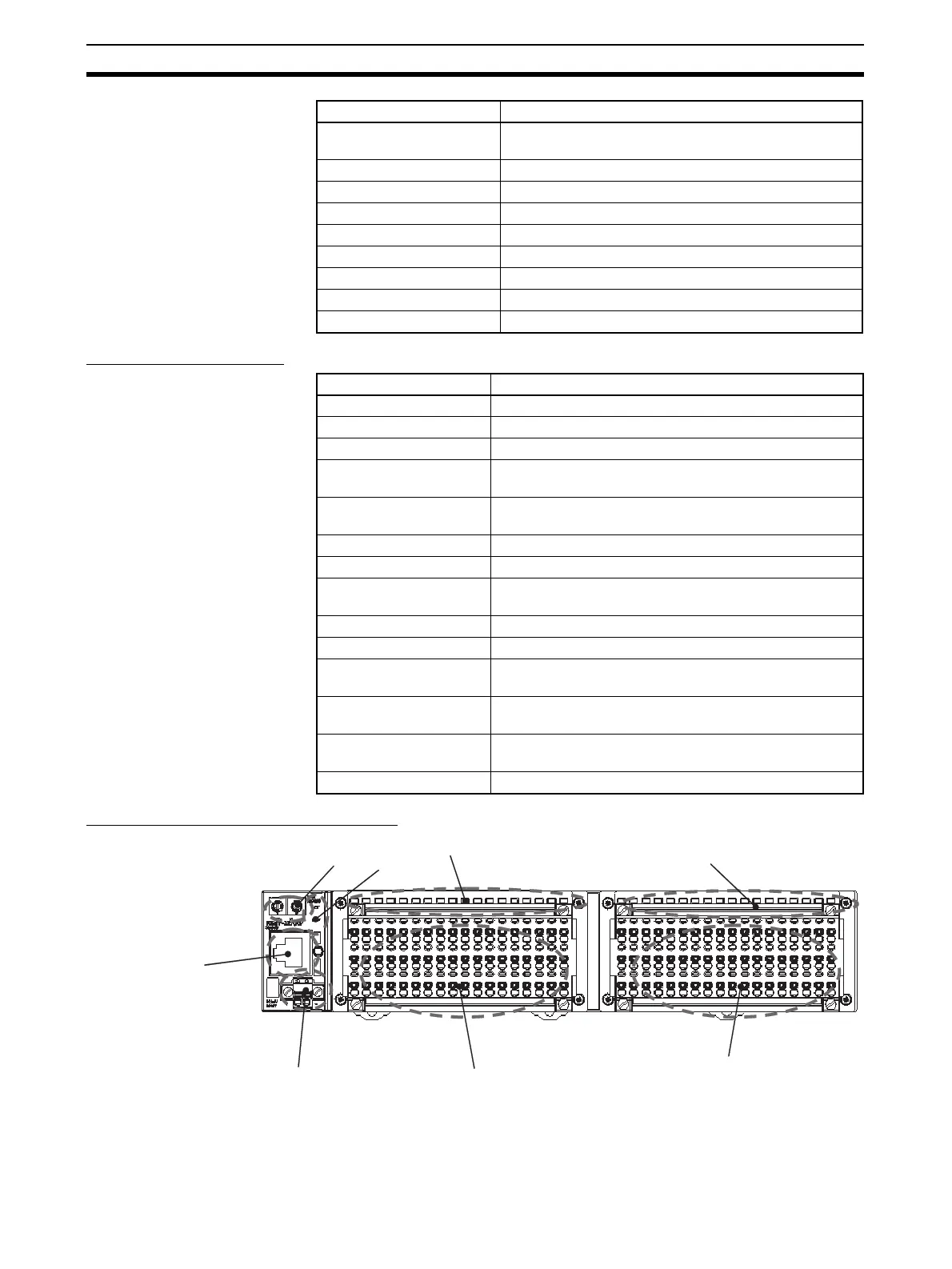
Component Names and Functions
(1) Rotary Switches
These switches are used to set the node address.
Input current 6.0 mA max. at 24 V DC
3.0 mA max. at 17 V DC
ON delay time 1.5 ms max.
OFF delay time 1.5 ms max.
Number of circuits 16 points with one common circuit
Isolation method Photocoupler isolation
Input indicators LEDs (yellow)
Power supply short-circuit Operates at 50 mA/point min.
Disconnection detection Operates at 0.2 mA/point max.
Connection forms Screw-less clamp terminal blocks (orange)
Item Specifications
Item Specification
Output points 16 points
Internal I/O common PNP
Output current 0.5 A/point, 4.0 A/common
Residual voltage 1.2 V max. (0.5 A DC, between each output terminal and
the V terminal)
Leakage current 0.3 mA max. (24 V DC, between each output terminal
and the V terminal)
ON delay 0.5 ms max.
OFF delay 1.5 ms max.
Number of circuits per
common
16 outputs/common
Isolation method Photocoupler
Output indicators LEDs (yellow)
Power supply short-circuit
protection
Operates when output current is exceeded.
Disconnection detection Operates at current consumption of 3 mA/point max. (Not
detected at 3 mA or less.)
Output handling for com-
munications errors
Select either hold or clear from Network Configurator.
Connection forms Screw-less clamp terminal blocks (yellow)
(1)
(2)
(3)
(4)
(5)
(6)
(7)
(8)
 Loading...


