66
Environment-resistive Slave Units Section 5-2
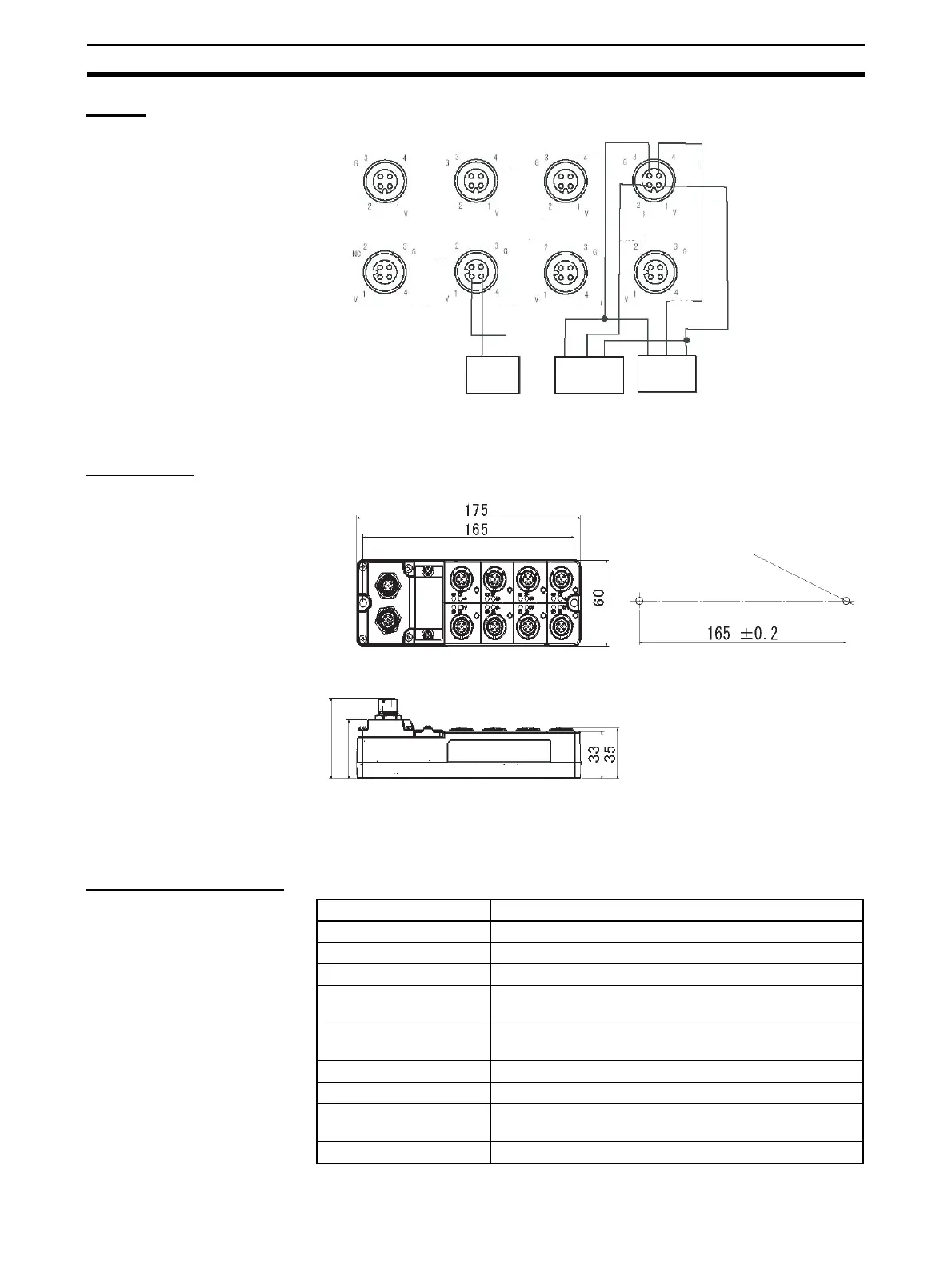
Wiring
Dimensions
5-2-3 Environment-resistive Terminals with 16 Transistor Outputs (IP67)
ERT1-WD16CH-1
Output Specifications
Input 3
Input 2
Input 7
Input 1
Input 0
Input 6
Input 5
Input 4
Input 10
Input 9
Input 8
Input 11
Input 14
Input 15
Input 12
Input 13
Brown (white)
Blue (black)
2-wire sensor
(e.g., limit switch)
3-wire sensor with
PNP output
(photoelectric sensor
or proximity sensor)
3-wire sensor with
PNP output
(photoelectric sensor
or proximity sensor)
Blue (black)
Brown (red)
Black (white)
Blue (black)
Brown (red)
Black (white)
Two, M5 or 5.3-dia. holes
Item Specification
Output points 16 points
Internal I/O common PNP
Output current 0.5 A/point, 4.0 A/common
Residual voltage 1.2 V max. (0.5 A DC, between each output terminal and
the V terminal)
Leakage current 0.3 mA max. (24 V DC, between each output terminal
and the V terminal)
ON delay 0.5 ms max.
OFF delay 1.5 ms max.
Number of circuits per
common
16 outputs/common
Isolation method Photocoupler
 Loading...


