65
Environment-resistive Slave Units Section 5-2
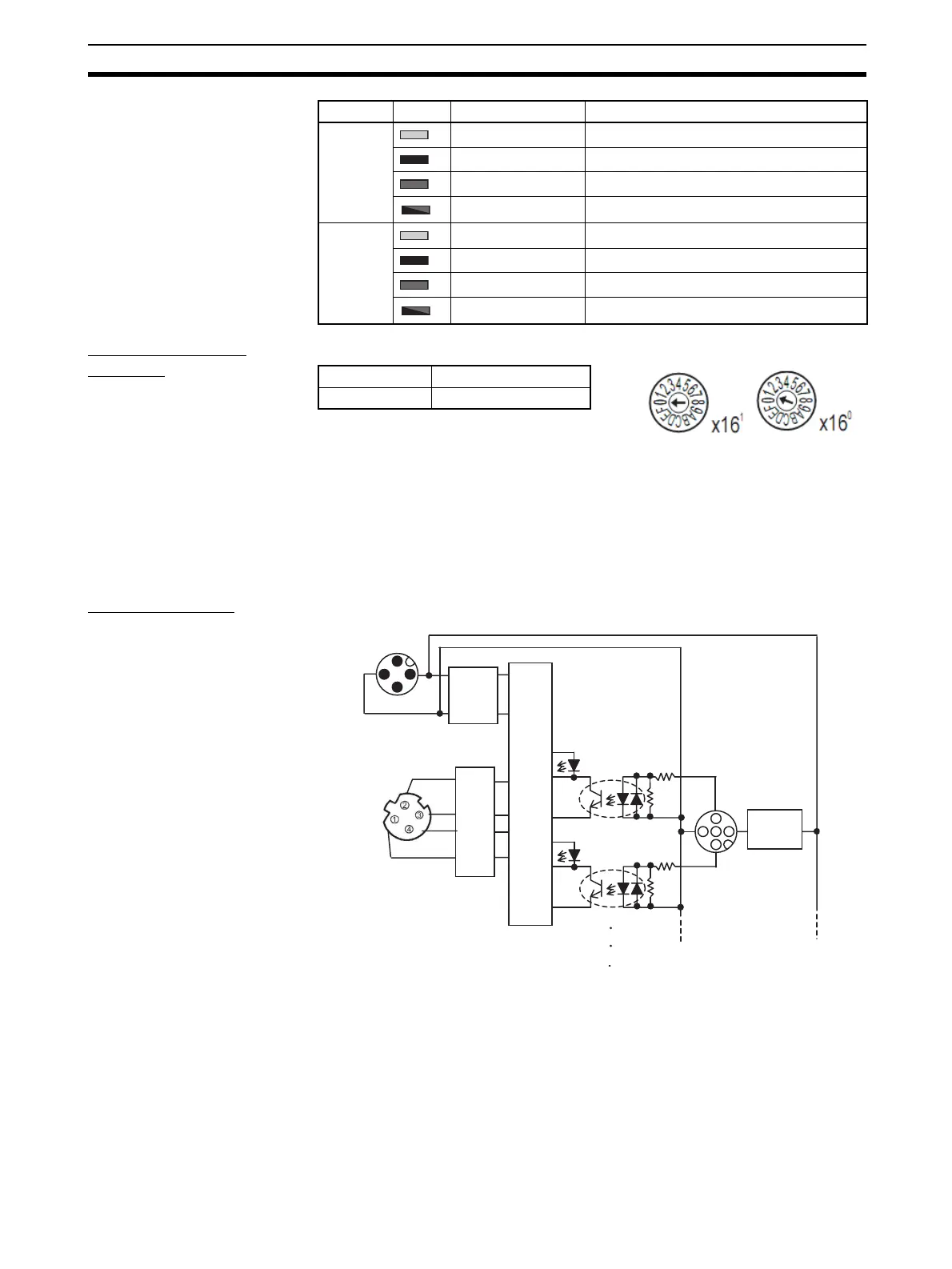
Setting the Node
Address
The rotary switches are used to set the lower digits of the IP address.
Rotary Switch Settings
00 hex: BOOTP or tool setting enabled (factory setting)
01 to FE hex: Setting on rotary switches is lower 8 bits of IP address. (De-
fault setting of upper 24 bits: 192.168.250.)
FF hex: Restores default setting.
(To restore the default setting, set the switches to FF hex, cycle the power
supply, and then set the switches to 00 hex.)
Internal Circuits
8-A Lit yellow. Input 4 is ON.
Not lit. Input 14 is OFF.
Lit red. Connector 8 is short-circuited.
Flashing red. Connector 8 is disconnected.
8-B Lit yellow. Input 15 is ON.
Not lit. Input 15 is OFF.
Lit red. ---
Flashing red. ---
Indicator Color Status Meaning (main error)
Setting method Two hexadecimal digits
Setting range 01 to FE
Photocoupler
I/O indicator
1
5
3
4
I/O indicator
Photocoupler
DC-DC
converter
(non-
isolated)
Short-circuit or
disconnection
detection circuit
Internal
circuits
Pulse
trans-
former
2
 Loading...


