47
Screw-less Clamp Terminals Section 4-2
4-2-2 Thirty-two-point Input Units (with Screw-less clamps)
ERT1-ID32SLH-1
Input Specifications
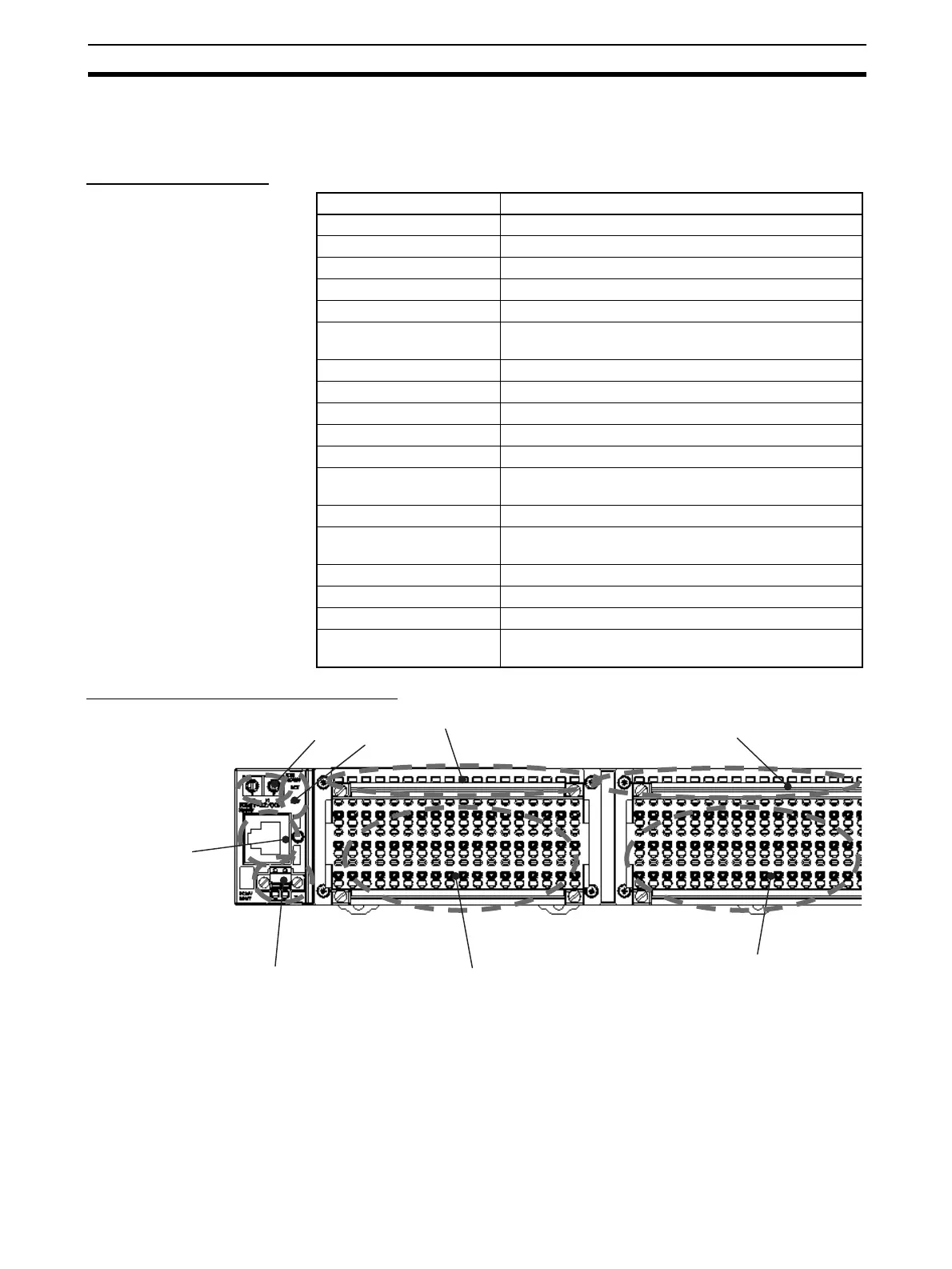
Component Names and Functions
(1) Rotary Switches
These switches are used to set the node address.
(2) Ethernet Connector
The network communications cable is connected to this connector.
Item Specifications
Input points 32 points
Internal I/O common PNP
ON voltage 15 V DC min. (between each input terminal and 0 V)
OFF voltage 5 V DC max. (between each input terminal and 0 V)
OFF current 1.0 mA max.
Input current 6.0 mA max. at 24 V DC
3.0 mA max. at 17 V DC
ON delay time 1.5 ms max.
OFF delay time 1.5 ms max.
Number of circuits 16 points with one common circuit
Isolation method Photocoupler isolation
Input indicators LEDs (yellow)
Power supply short-circuit
protection
Operates at 50 mA/point min.
Disconnection detection Operates at 0.2 mA/point max.
Current consumption Communications power supply (including internal cir-
cuits): 110 mA max.
Connection forms Screw-less clamp terminal blocks (orange)
Mounting 35-mm DIN Track mounting
Weight 485 g max.
Standard accessories FKMCP1.52STF3.5AUSOO (Phoenix Contacts) (con-
nector with lock screws)
(1)
(2)
(3)
(4)
(5)
(6)
(7)
(8)
 Loading...


