45
Screw-less Clamp Terminals Section 4-2
4-1-2 I/O Status Area
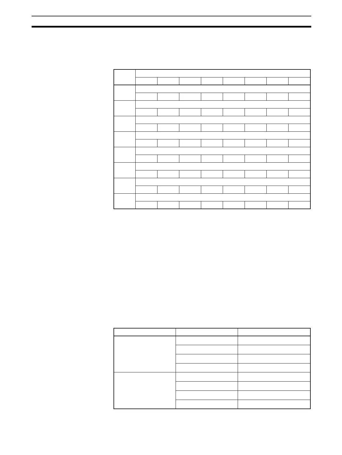
The I/O Status Area for a Digital I/O Slave Unit consists of the following 8
bytes (64 bits). The I/O Status Area indicates the short-circuit and disconnec-
tion error status for each terminal.
4-2 Screw-less Clamp Terminals
The screw-less clamp terminal has a structure designed for clamping to a ter-
minal block. It is a reduced-wiring, labor-saving Slave that can make wiring
easy by simply inserting ferrules (with sleeves). The Unit and terminal block
can be detached, making it possible to replace the Unit in the event of a failure
without removing the wiring.
A detection function is also provided to help quickly discover short-circuits and
disconnections for sensors or other devices.
4-2-1 Wiring to a Screw-less Clamp Terminal Block
Screw-less clamp terminals provide clamp-type terminal blocks that allow wir-
ing without screws. When connecting a sensor or an external device, a ferrule
must be attached to the cable for the sensor or device. The following ferrules
are applicable.
Byte
offset
Data
Bit 07 06 05 04 03 02 01 00
0 Power or Load Short-circuit Detection Flags for Terminal Block 1
07 06 05 04 03 02 01 00
1 Power or Load Short-circuit Detection Flags for Terminal Block 1
15 14 13 12 11 10 09 08
2 Power or Load Short-circuit Detection Flags for Terminal Block 2
07 06 05 04 03 02 01 00
3 Power or Load Short-circuit Detection Flags for Terminal Block 2
15 14 13 12 11 10 09 08
4 Disconnection Flags for Terminal Block 1
07 06 05 04 03 02 01 00
5 Disconnection Flags for Terminal Block 1
15 14 13 12 11 10 09 08
6 Disconnection Flags for Terminal Block 2
07 06 05 04 03 02 01 00
7 Disconnection Flags for Terminal Block 2
15 14 13 12 11 10 09 08
Manufacturer Model
Phoenix Contact AI-0.5-10
0.5 mm
2
(AWG 20)
AI-0.75-10
0.75 mm
2
(AWG 18)
AI-1.5-10
1.25 mm
2
(AWG 16)
AI-2.5-10
2.0 mm
2
(AWG 14)
Nihon Weidmuller H 0.5/16 D
0.5 mm
2
(AWG 20)
H 0.75/16 D
0.75 mm
2
(AWG 18)
H 1.5/16 D
1.25 mm
2
(AWG 16)
H 2.5/16 D
2.0 mm
2
(AWG 15)
 Loading...


