50
Screw-less Clamp Terminals Section 4-2
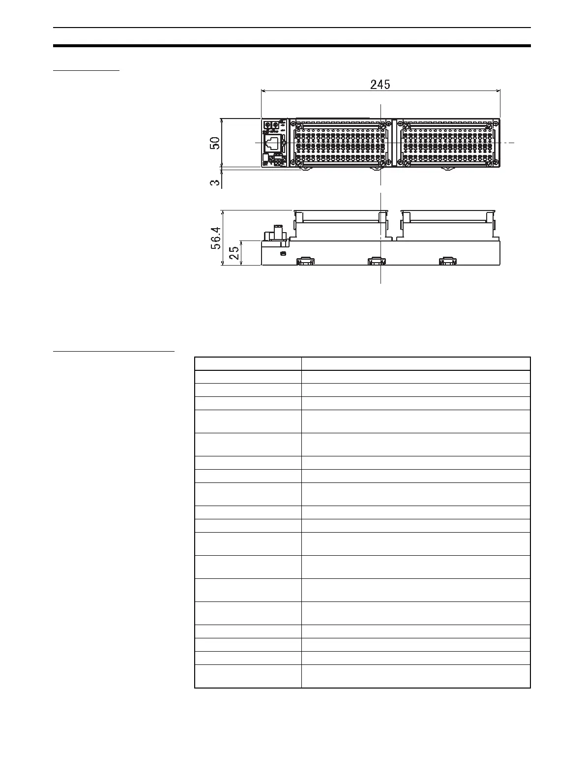
Dimensions
4-2-3 Thirty-two-point Output Units (with Screw-less Clamps)
ERT1-OD32SLH-1
Output Specifications
Item Specification
Output points 32 points
Internal I/O common PNP
Output current 0.5 A/point, 4.0 A/common
Residual voltage 1.2 V max. (0.5 A DC, between each output terminal and
the V terminal)
Leakage current 0.3 mA max. (24 V DC, between each output terminal
and the V terminal)
ON delay 0.5 ms max.
OFF delay 1.5 ms max.
Number of circuits per
common
16 outputs/common
Isolation method Photocoupler
Output indicators LED (yellow)
Power supply short-circuit
protection
Operates when output current is exceeded.
Disconnection detection Operates at current consumption of 3 mA/point max. (Not
detected at 3 mA or less.)
Output handling for com-
munications errors
Select either hold or clear from Network Configurator.
Current consumption Communications power supply (including internal cir-
cuits): 120 mA max.
Connection forms Screw-less clamp terminal blocks (yellow)
Mounting 35-mm DIN Track mounting
Weight 485 g max.
Standard accessories FKMCP1.52STF3.5AUSOO (Phoenix Contacts) (connec-
tor with lock screws)
 Loading...


