51
Screw-less Clamp Terminals Section 4-2
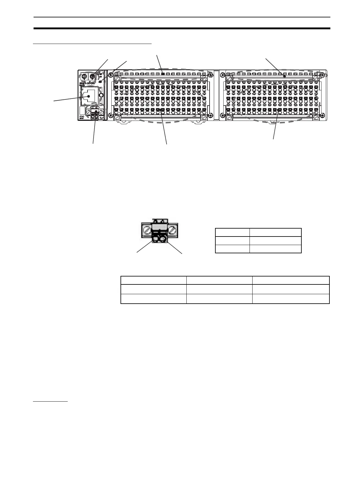
Component Names and Functions
(1) Rotary Switches
These switches are used to set the node address.
(2) Ethernet Connector
The network communications cable is connected to this connector.
(3) Power Supply Connector
The communications and Unit power supply is connected to this connector.
Applicable Ferrules
(4) Communications Indicators: MS and NS
These indicators show the Unit communications status and network commu-
nications status.
(5) and (6) Terminal Blocks 1 and 2
The output devices and output power supply are connected to these terminal
blocks.
(7) and (8) Output Indicators
These indicators show the ON/OFF status of the outputs and the error status
of connected devices.
Indicators
Communications
Indicators
Refer to 3-1-3 Communications Indicators.
(1)
(2)
(3)
(4)
(5)
(6)
(7)
(8)
Manufacturer Model Applicable wire size
Phoenix Contact AI-0.5-10
0.5 mm
2
(AWG 20)
Nihon Weidmuller H 0.5/16 D
0.5 mm
2
(AWG 20)
24 V DC
0 V DC
Terminal Specification
+ 24 V DC
− 0 V DC
 Loading...


