52
Screw-less Clamp Terminals Section 4-2
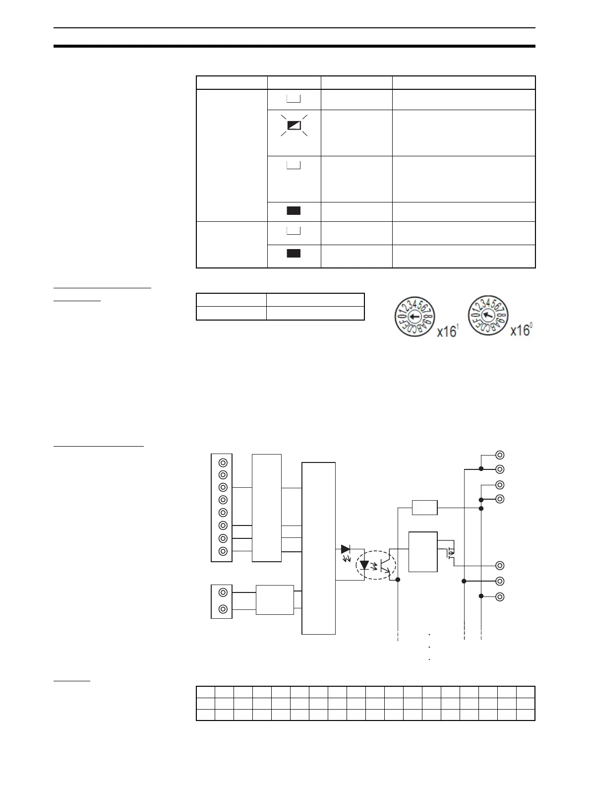
I/O Indicators The meanings of the input indicators are given in the following table.
Setting the Node
Address
The rotary switches are used to set the lower digits of the IP address.
Rotary Switch Settings
00 hex: BOOTP or tool setting enabled (factory setting)
01 to FE hex: Setting on rotary switches is lower 8 bits of IP address. (De-
fault setting of upper 24 bits: 192.168.250.)
FF hex: Restores default setting.
(To restore the default setting, set the switches to FF hex, cycle the power
supply, and then set the switches to 00 hex.)
Internal Circuits
Wiring
Indicator name Status Color Meaning (main error)
0 to 15 Yellow Lit yellow when output is ON.
Red Flashing red when the load is dis-
connected.
Automatically reset when the load
is connected.
Red Lit red when the load is short-cir-
cuited.
Automatically reset when the
short-circuit is removed.
OFF Not lit when output is OFF.
I/O Green Lit green when I/O power is being
supplied.
OFF Not lit when I/O power is not being
supplied.
Setting method Two hexadecimal digits
Setting range 01 to FE
NC
TD−
RD+
TD+
NC
RD−
NC
NC
V+
V−
0 to 15
Photocoupler
I/O indicator
V
G
V
G
V
G
1
6
7
8
DC-DC
converter
(non-isolated)
Short-circuit
or
disconnection
detection
circuit
Voltage
drop
Internal
circuits
Pulse
trans-
former
NC0123456789101112131415NC
VVVVVVVVVVVVVVVVVV
GGGGGGGGGGGGGGGGGG
 Loading...


