11
Overview of System Startup Procedure Section 2-1
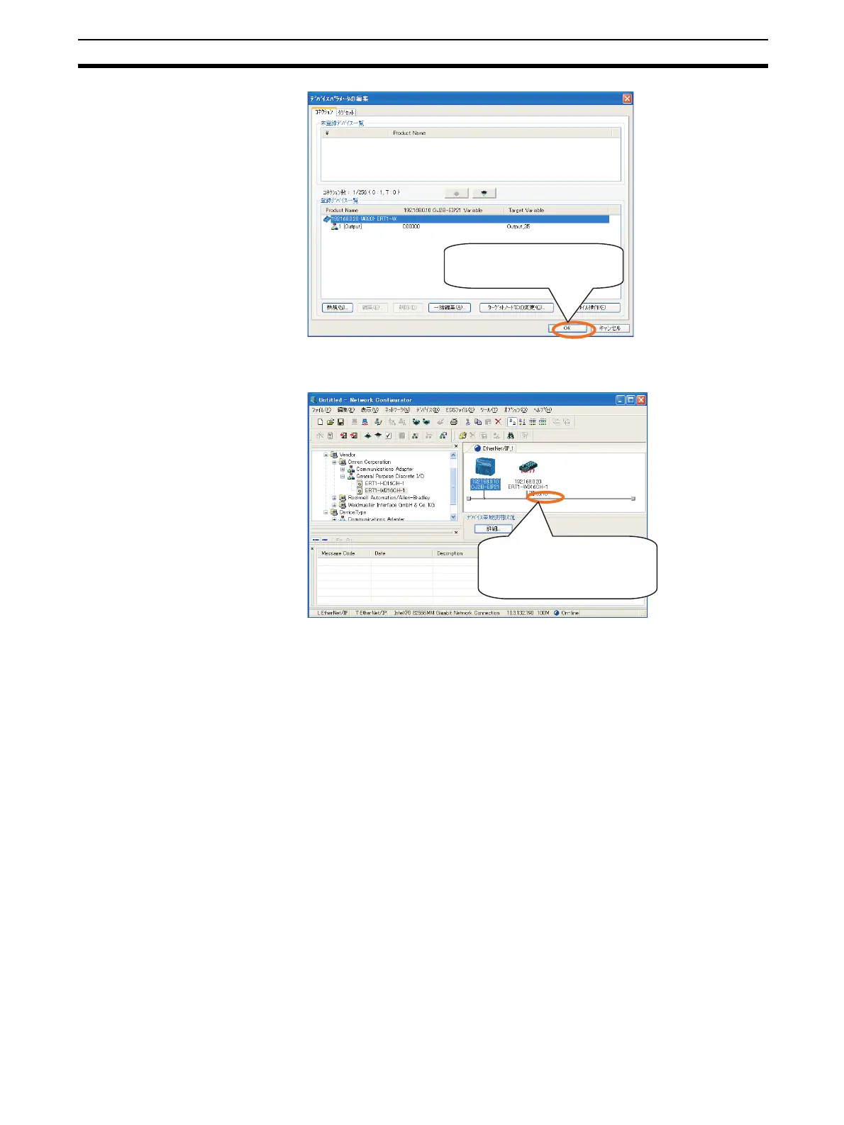
After a connection has been set, a window like the one shown below will
be displayed.
When the above window is displayed, setting the connection has been
completed.
3. Write the connection settings to the devices.
Refer to Common Procedure 7-4. Downloading Connection Settings to De-
vices.
2-1-4 Checking Operation
Make sure that tag data link is operating normally.
■ EtherNet/IP Unit
Check the display and indicators on the EtherNet/IP Unit. The following status
indicates that tag data link is operating normally.
• MS indicator: Lit green.
• NS indicator: Lit green.
• 7-segment display: Shows the rightmost digits of the EtherNet/IP Unit
node address in hexadecimal (0A would be displayed for address
192.168.0.10).
■ EtherNet/IP Slave Unit
Check the indicators on the Slave Unit. The following status indicates that tag
data link is operating normally.
• MS indicator: Lit green.
Click the OK Button to enable the
settings.
This mark will be displayed when
a connection has been set.
 Loading...


