49
Screw-less Clamp Terminals Section 4-2
01 to FE hex: Setting on rotary switches is lower 8 bits of IP address. (De-
fault setting of upper 24 bits: 192.168.250.)
FF hex: Restores default setting.
(To restore the default setting, set the switches to FF hex, cycle the power
supply, and then set the switches to 00 hex.)
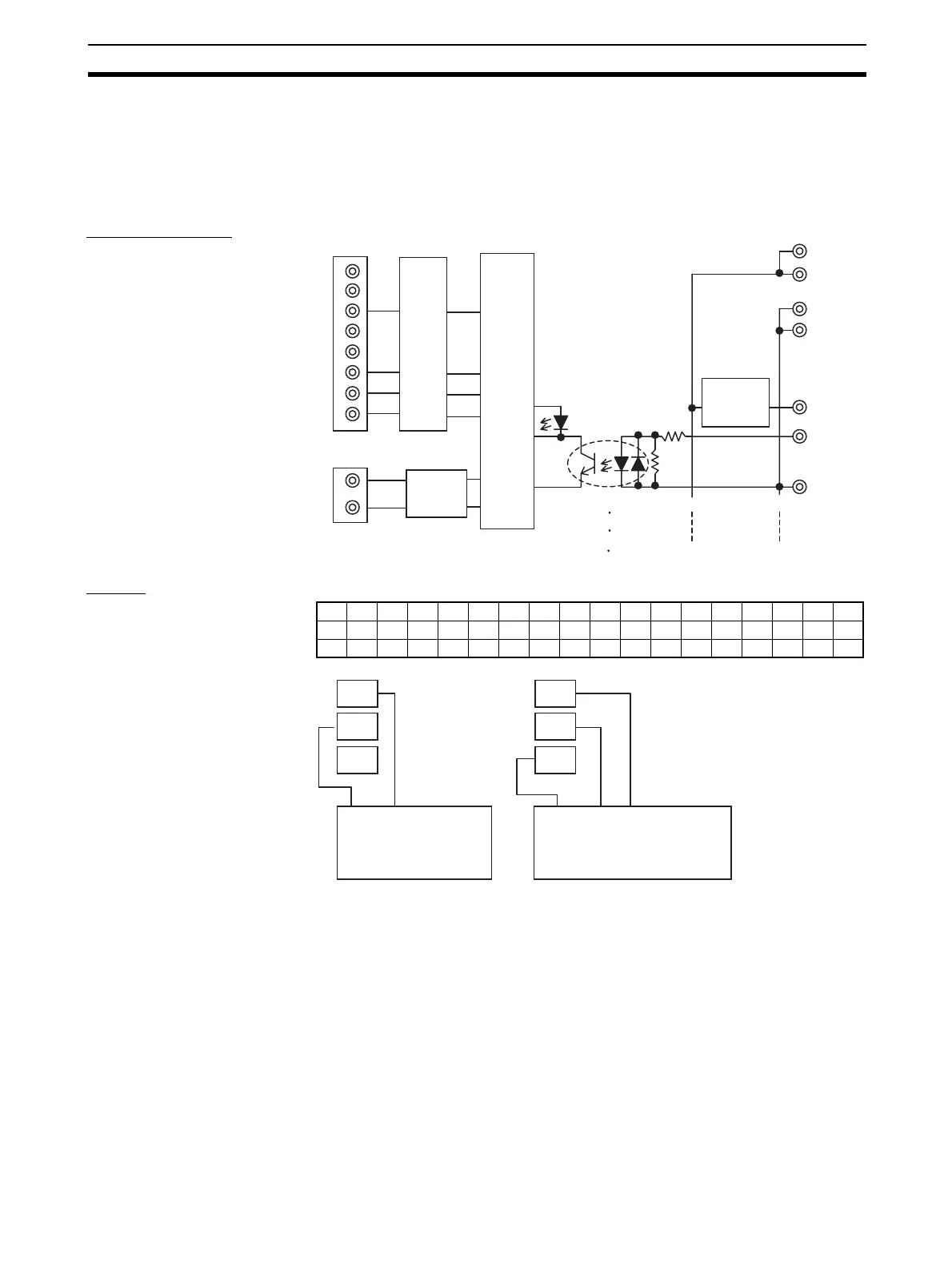
Internal Circuits
Wiring
NC
TD−
RD+
TD+
1
V
G
G
V
G
6
7
8
NC
RD−
NC
NC
V+
V−
0 to 15 VDC
0 to 15
Photocoupler
I/O indicator
Internal
circuits
DC-DC
converter
(non-isolated)
Short-circuit or
disconnection
detection circuit
Pulse
trans-
former
NC0123456789101112131415NC
V V0V1V2V3V4V5V6V7V8V9V10V11V12V13V14V15V
GGGGGGGGGGGGGGGGGG
X
VX
G
X
VX
G
3-wire sensors
(photoelectric or proximity sensors)
Brown
(White)
Blue
(Black)
(IEC colors)
(Previous
colors)
2-wire sensors
(2-wire proximity sensors)
X: 0 to 15
(IEC colors)
(Previous
colors)
Blue
(Black)
Brown
(Red)
Black
(White)
 Loading...


